
Pneumatic System Components: How a Complete Air-Power System Is Built
Pneumatic system components are the full set of devices that turn a compressor’s output into controlled, useful motion. Knowing the pneumatic system components in sequence helps engineers design lines that are safe, efficient, and easy to maintain. In this guide, we walk through a typical system from source to actuator.
Why a System View Matters
A single valve rarely works alone. Instead, pneumatic system components form a chain in which each stage affects the next. For instance, poor air preparation shortens valve life. Therefore, designing the whole chain beats optimizing one part in isolation.
The Pneumatic System Components in Order
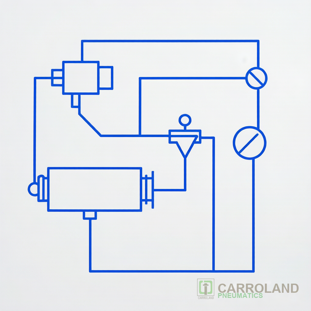
The chain begins with the compressor and air receiver. Next, the preparation stage (FRL) cleans and regulates the air. Then, the control stage routes flow through solenoid valves and manifolds. Finally, the actuation stage drives cylinders and grippers. In addition, tubing, silencers, and sensors connect and protect the loop. Our 3C automation pneumatic systems overview shows this chain on a real line.
Sizing the Pneumatic System Components
Sizing follows the demand of the largest simultaneous load. First, total the flow of all actuators. Then size the compressor and main line with margin. Finally, select FRL ratings above the peak flow. Specifically, undersized preparation causes pressure drops that stall cylinders and slow cycles.
Component Sizing Reference
| Stage | Size by | Risk if undersized |
|---|---|---|
| Compressor | Peak free air delivery | Pressure sag, stall |
| FRL | Flow at set pressure | Contaminated, unstable air |
| Main line | Total Kv demand | Pressure drop |
| Valve | Actuator Kv + speed | Slow or weak motion |
| Cylinder | Force = bore × pressure | Insufficient clamp |
Linking Components to Standards
Cylinders use ISO 15552 or ISO 6432. Valves follow ISO 15217-1. Air quality follows ISO 8573-1. Consequently, matching every pneumatic system component to its standard simplifies spare parts and upgrades. For a deeper read on air preparation, see our complete FRL guide.
Maintenance Across the System
Plan maintenance by wear rate, not by calendar alone. For example, drain FRL bowls weekly and replace filter elements per hours. Similarly, log cylinder cycle counts to time seal kits. As a result, a small spares kit avoids long stops.
Energy Efficiency Across Components
Compressed air is expensive, so the system view pays off. First, fix leaks, which can waste 20% of generation. Then right-size cylinders so they use only the force needed. Finally, add sequencers that shut air to idle stations. Specifically, a meter-out speed control on each cylinder trims overshoot and saves air without slowing the useful stroke.
Safety and E-Stop Integration
Safety-rated valves and quick-exhaust fittings make a fixture drop fast on e-stop. For instance, a normally closed valve releases the clamp the moment power fails. Moreover, dual-channel feedback proves the part is clear before a robot enters. Therefore, the component choice directly affects machine-safety ratings on the line.
Digital Pneumatics and IIoT
Smart manifolds log cycle counts and pressure trends. As a result, maintenance shifts from calendar to condition based. Furthermore, cloud dashboards flag a drifting regulator before it starves a station. Our custom pneumatics team helps retrofit these onto existing lines without a full rebuild.
Frequently Asked Questions
What is the most overlooked pneumatic system component?
The FRL unit. Although small, it protects every downstream device. As a result, skipping it causes early valve failure.
Which pneumatic system components fail first?
Seals and filter elements wear fastest. Therefore, a planned maintenance schedule pays back quickly.
How do I reduce air consumption across components?
Size cylinders to the real force needed, add quick-exhaust valves, and fix leaks. Our cylinder sizing and air-consumption guide shows the math.
Sizing Example: A Two-Clamp Fixture
Suppose two clamps need 200 N each at 6 bar. First, solve bore from force = pressure × area, which gives about 21 mm, so choose 25 mm. Then size the FRL for both cylinders’ peak flow plus 30% margin. Finally, pick a valve with Kv above the demand. Specifically, this method prevents the sag that slows the second clamp. As a result, a simple calc saves a rebuild.
Common System Mistakes
Teams often run one oversized compressor for the whole plant, then wonder why the far line sags. Moreover, they skip the FRL to save cost and pay in valve swaps. Therefore, size local preparation at the load, not at the source alone.
How do I calculate total air demand?
Sum each actuator’s volume per stroke times cycles per minute, then add 20% for leaks. Our sizing guide shows the formula.
Can I add components later without redesign?
Yes if you leave spare ports and margin in the FRL and main line. Consequently, planning 20% headroom lets you grow the cell.
What pressure is typical for automation?
Most 3C lines run 4–7 bar. Higher pressure wastes air; lower stalls clamps. Therefore, regulate to the real need.
Why does my system hiss at idle?
A constant hiss usually means a bleed or a leaking seal somewhere downstream. Therefore, a soap-bubble test on joints finds it fast.
How often should I service the system?
Drain FRL bowls weekly, replace filter elements per running hours, and log cylinder cycles for seal kits. Therefore, a simple log turns surprises into planned stops.
What documentation should travel with the system?
Keep the P&ID, the component codes, and the spares list at the cell. As a result, any shift can fix a fault without a call to engineering.
Related: FRL air preparation guide and custom pneumatics for 3C automation.
Standard: ISO 8573-1 compressed air quality.