
How an FRL Unit Works: Filter, Regulator and Lubricator Principles for Pneumatic Systems
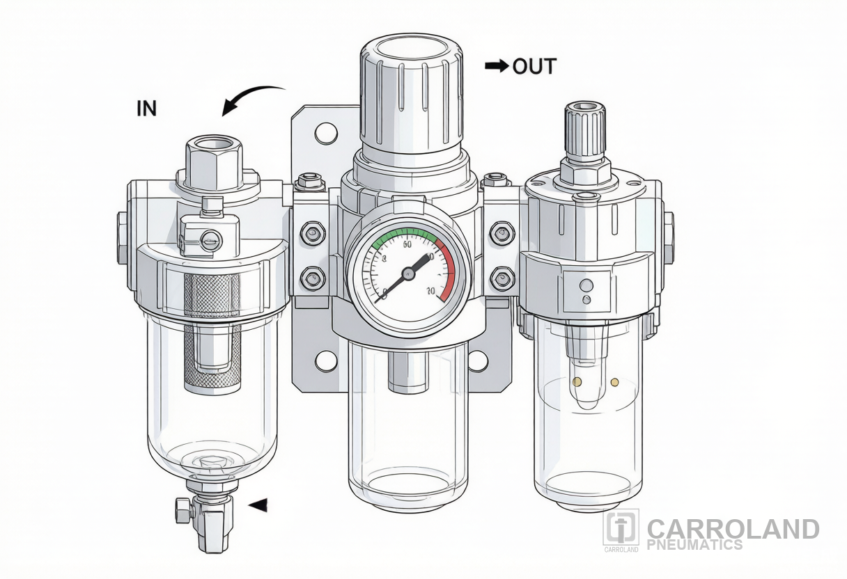
If you walk into a well-run pneumatic line, the first thing you find upstream of every valve island is an air preparation unit built around three components bolted together: a filter, a regulator, and a lubricator. Together they form what the industry calls an FRL unit, and understanding the FRL unit working principle is what separates a pneumatic system that runs for ten years from one that fails seals in six months.
On Carroland-equipped lines the FRL station is consistently the lowest-cost component per cubic metre of air it serves, and it is almost always the first thing we audit when a customer reports shortened seal life or unstable cylinder stroke timing. Consequently, getting this stage right pays back across every valve, cylinder and seal that sits downstream.
This guide explains the working principle stage by stage, then links it back to the rest of the air treatment chain. Specifically, dried air from the compressor, regulated pressure at the working port, and metered lubrication reaching each downstream valve and cylinder.
Where the FRL Sits in the Compressed Air System
Bulk Treatment vs Point-of-Use
A complete compressed air system delivers air at a quality and pressure the end device can actually use. ISO 8573-1:2010 — currently in stage 90.92 (to be revised) and being succeeded by ISO/AWI 8573-1 — defines purity across three contaminant groups: solid particles, water, and oil, written as a three-part class like [1:2:1]. For the working classes a maintenance team needs to remember on the line, see our ISO 8573-1 air quality classes guide; for the broader FRL configuration context, our pneumatic FRL air preparation guide covers port sizing and drain selection in detail.
- Compressor — pressurises atmospheric air and rejects roughly 85–90% of the electrical input as heat.
- Aftercooler + moisture separator — drops the air temperature close to ambient and drops out bulk liquid water.
- Receiver tank — buffers demand peaks and lets condensate settle.
- Desiccant or refrigerated dryer — brings the pressure dew point down to the class the application requires (for example +3 °C PDP for ISO 8573-1 water Class 4).
- Air preparation unit (FRL) — final filtration, pressure regulation, and lubrication at the point of use.
In short, the FRL sits at the boundary between bulk treatment and point-of-use treatment. Bulk equipment looks after volume; the FRL looks after the last few metres of hose and the next hour of operation.
The Three Stages of the FRL Unit Working Principle
An FRL is a modular assembly, and each stage has a distinct mechanism. We will walk through the working principle in the order the air actually sees them.
Stage 1 — The Filter Stage
First, bulk dryers remove most of the liquid water, but they do not strip every aerosol, and they do nothing about solid particles. The filter stage catches what is left. Typical specifications on a 1/4″ modular FRL are:
| Specification | Standard Range | Notes |
|---|---|---|
| Filtration grade | 5 / 25 / 40 µm | 5 µm for valves and instrument air; 40 µm general; 0.01–0.1 µm for coalescing oil removal |
| Filter bowl capacity | 22–200 cm³ | Scales with port size: 22 cm³ at 1/4″, 100 cm³ at 1/2″, 200 cm³ at 3/4″ |
| Bowl material | Polycarbonate (with guard) / aluminum | Use aluminum in hot or solvent-exposed zones |
| Drain type | Manual / semi-auto / float auto / timed solenoid | Auto drains recommended when the line runs continuously |
Specifically, a standard 40 µm element works as a mechanical barrier — air enters the bowl and is forced through a sintered bronze or PE sintered element, where particulates above the rated size collide and adhere to the matrix. A 5 µm element does the same at higher pressure drop. Coalescing filters go further: they capture liquid aerosols by impaction and are typically rated at 0.01 mg/m³ residual oil content, which lines up with ISO 8573-1 oil Class 1.
Two practical rules keep the filter stage honest:
- Always mount the bowl vertical with the drain at the bottom — condensate will not fall out of a sideways bowl.
- Replace the element when the differential pressure (ΔP) across it climbs — many datasheets specify a 0.5 to 0.7 bar ΔP threshold. Above that, the filter becomes a flow restriction and the downstream regulator starts drooping.
Stage 2 — The Regulator Stage
Next, the regulator is the component that turns the upstream supply (often 7–10 bar) into the working pressure the device actually needs (typically 5.5–6.0 bar on cylinder lines, lower on solenoid pilot lines). Most modular regulators use a rolling-diaphragm or piston design with a self-relieving option as standard.
Specification ranges you will see on a current modular regulator:
| Specification | Standard Range | Application Mapping |
|---|---|---|
| Outlet pressure window | 0.5–10 bar (standard); 0.5–30 bar (high-pressure) | Pick a window whose setpoint sits in the upper third for best droop behaviour |
| Maximum inlet pressure | 10 bar (polycarbonate) / 14 bar (aluminum bowl) / 16 bar (high-pressure) | Match the bowl material to the supply pressure |
| Regulation accuracy (rolling diaphragm) | ±3% FSD typical; ±2% FSD in the 8–12 bar window | Tighter than piston regulators on the same body |
| Relieving vs non-relieving | Self-relieving standard; non-relieving optional | Use non-relieving when downstream venting would disturb the process (e.g. closed-loop tension control) |
In practice, the working principle is straightforward: inlet pressure acts on the underside of the diaphragm; the operator turns the adjusting knob to set the spring force on top; the valve opens or closes until the two forces balance. If downstream pressure drops (because a cylinder extends and draws flow), the diaphragm flexes, the valve opens more, and the output recovers. If downstream pressure rises (because a valve closes), the self-relieving version vents a small amount of air through the relief port until balance returns. As a result, this feedback loop is what keeps compressed air cylinder pressure stable during cycling, even when the receiver or the compressor cannot keep up.
One detail that gets misapplied: every additional 1 bar of setpoint above what the device needs adds roughly 7% to compressor energy use. For example, if your line is set at 7 bar but the cylinder only needs 5 bar, you are paying for an invisible leak that looks like electricity. We see plants save 8–15% on the compressed air line item alone by trimming setpoints after the FRL is properly regulated.
Stage 3 — The Lubricator Stage
Finally, the lubricator stage meters a small amount of oil into the airstream. The goal is not to flood the device with oil — it is to keep a thin film on every moving seal and bushing downstream. The lubricator works on the venture principle: a small pressure differential generated by the airflow across a nozzle lifts oil from the bowl into a fine mist.
Typical dosing and operating limits:
| Parameter | Typical Value | Why it matters |
|---|---|---|
| Oil type | ISO VG 32 petroleum, non-detergent | Detergent oils leave residue; synthetics may swell NBR seals; never use motor oil or WD-40 |
| Dose | 1 drop per 300–600 L of airflow | Visible-drop check on the sight dome confirms active dosing |
| Lubricator bowl capacity | 42–440 cm³ by port size | Refill interval scales with cycle count and oil flow setting |
| Minimum flow | Manufacturer-specific, often 0.5 L/s ANR | Below this, the venture effect collapses and no oil is drawn |
| Operating temperature | −10 °C to +60 °C (standard); −40 °C option | Cold starts starve the lubricator until air warms up |
Modern oil-less valves and cylinders with pre-lubricated PTFE seals do not need the L stage. In clean-room, food-contact and pharmaceutical lines the L is left out because any oil aerosol would be a contamination vector, and a coalescing filter is added in its place. In contrast, for most general industrial lines the L stays in and the rotary oil film it produces is what lets a standard compressed air valve actuator reach a million cycles without seal replacement.
FRL Configurations You Will Actually Meet on a Factory Floor
In practice, not every pneumatic system uses a full three-stage assembly. The four configurations we see most often:
- FR (Filter + Regulator only) — preferred in food, pharma, semiconductor, and any oil-free line. The “L” is replaced by a coalescing filter rated at 0.01 mg/m³ residual oil.
- 3-piece FRL — the standard configuration for general factory pneumatics. Modular bowls are joined by face connectors and mounted on a single bracket.
- Modular FRL series — where each function is a separate module that clips into the next. An FRL fitting face connector locks the filter, regulator and lubricator into a single bracket-mounted assembly, and the same connector pattern lets a service engineer pull one module out for element replacement or bowl cleaning without disturbing the rest of the line.
- Individual components — separate filter, separate regulator, separate lubricator, piped together. Used when one stage needs to be remote (for example, a dryer in a plant room and a regulator at the machine).
For example, on Carroland-supplied iPhone-line solutions, we see the FR (no L) configuration as the default upstream of the clamping solenoid manifolds. PTFE-sealed cylinders downstream of the manifold do not need a constant oil film, and the absence of an aerosol cuts carry-over onto plastic and glass parts.
Matching Port Size to Air Demand
The single most common FRL sizing error is choosing the port size by the thread size of the hose, not by the actual demand. The rule of thumb that holds up across our reference installations:
| Port size | Approximate nominal flow (SCFM) | Reference flow (L/min ANR) | Typical duty |
|---|---|---|---|
| 1/4″ BSP / NPT | ~30 SCFM | ~850 L/min ANR | Single-tool drops, small fixture islands |
| 3/8″ BSP / NPT | ~60 SCFM | ~1,500 L/min ANR | Compact work-station manifolds, 2–4 actuators |
| 1/2″ BSP / NPT | ~100 SCFM | ~2,310 L/min ANR | Main valve island, mid-size clamping fixtures |
| 3/4″ BSP / NPT | ~150 SCFM | ~4,200 L/min ANR | Multi-station assembly lines |
| 1″ BSP / NPT | ~200+ SCFM | ~5,800+ L/min ANR | Plant mains, central distribution |
However, these figures assume a 1–3 psi (0.07–0.21 bar) pressure drop at peak flow, which is the normal sizing band. If the design calls for less than 0.05 bar ΔP at peak, step the port up one size. A 1/2″ line serving 150 SCFM will reach setpoint, but the regulator will spend its life at full lift chasing the droop, and the diaphragm fails earlier than it should. For end-to-end line sizing including manifolds, take-offs and actuator stroke timing, see our pneumatic circuit design for automated production lines guide.
Pneumatic Air Line Connectors, Fittings and Hose Routing
Three Connector Families We Standardise On
Once the FRL delivers clean, regulated air into the distribution line, the connection hardware takes over. We standardise on three families of pneumatic air line connectors across Carroland-supplied systems:
- Push-to-connect fittings — 1/8″ to 1/2″ tube ODs, NBR or FKM seal, rated to 10 bar at 60 °C. Used on 80% of factory drops where the line never moves.
- Quick-release (1/4 turn) couplings — used at tool-change points, vacuum-pickup nozzles, and any station that needs to be isolated for maintenance.
- Threaded adapters and manifolds — BSP / NPT / Rc, brass or stainless 316. Used where the line is permanently piped and the fitting would never be removed.
Three Routing Rules We Never Bend
Pneumatic air lines and fittings also follow three routing rules we never bend:
- Maintain at least a 1% (1 in 100) downward slope toward the FRL so condensate drains back into the filter bowl, not downstream into the actuators.
- Use a separate take-off for each machine — never tee off a common manifold. If one machine drops its pressure on a cycle, the others should not see it.
- Keep the run from the FRL to the device under 3 metres where possible. Every extra metre of 8 mm hose adds roughly 0.01 bar of pressure drop at 100 L/min — small, but it adds up across 20 stations.
Additionally, pneumatic connectors air line fittings should be torqued to the manufacturer figure during installation and then re-checked at 100 hours, 1,000 hours, and after any process change that introduces vibration. A 1/4″ BSP fitting that was hand-tight at commissioning will be loose by the first thermal cycle if it was never torqued with a calibrated wrench.
Installation: Orientation, Distance and Drainage
The FRL working principle degrades quickly when the install is wrong. Five details that account for 90% of the FRL field issues we open up:
- Mount the assembly vertically with the bowl down. Horizontal or inverted mounting lets condensate pool against the seal and bypass the filter element.
- Mind the airflow arrow. A backwards FRL is silent until the regulator tries to relieve into its own inlet — at which point the relief port becomes an uncontrolled leak.
- Sequence Filter → Regulator → Lubricator. The acronym FRL is the order, not a stylistic choice. Lubricating before filtering loads the bowl with whatever the filter should have caught.
- Place the FRL within 3 metres of the device. A remote FRL protects the hose, not the valve. Long hose runs cool the air, drop the pressure, and let water re-condense before it reaches the device.
- Match drain type to duty cycle. Manual drains are fine on a 4-hour-shift line; an auto float or timer drain is required whenever the line runs overnight.
Consequently, an installation layout that follows these rules will show up in the audit data as a stable 6.0 bar setpoint with a 0.05 bar ΔP at peak and a clean sight dome for 6 months.
Maintenance Schedule That Actually Prevents Failures
The maintenance cycle we standardise on our lines, calibrated to the data we see across our customer base:
| Cadence | Action | Trigger to replace |
|---|---|---|
| Each shift | Crack manual drain / verify auto-drain operation; check gauge against setpoint | Gauge drift > 0.2 bar from setpoint |
| Weekly | Verify regulator lock-collar engaged; lubricator drip rate visible in sight dome | No drops in sight dome at expected flow |
| Monthly | Replace filter element; inspect O-ring; check bowl for stress cracks (polycarbonate only) | Element ΔP > 0.5 bar; any crazing visible on bowl |
| Quarterly | Wipe sight domes; check drain solenoid (electronic drains); re-torque threaded fittings to spec | Drain solenoid stuck open or closed on test cycle |
| Annually | Full depressurise, gasket kit replacement on the regulator and lubricator; verify ISO 8573-1 class at point of use | Measured class worse than [particles:water:oil] specification |
For example, on Carroland-supplied lines in India, where ambient dust and humidity push the upstream contamination harder, we shorten the monthly check to every 2 weeks on lines with a 40 µm element and every week on lines serving electronic-component pick-and-place stations, where a single particle event costs more than ten filter replacements. For a detailed analysis of how FRL air quality and lubrication settings affect cylinder seal longevity, see our pneumatic cylinder maintenance guide covering seal material selection and Weibull service life prediction.
The 7% Rule and Why Setpoint Matters
Where the 7% Comes From
Notably, the single largest energy lever on a pneumatic line is the regulator setpoint. The US Department of Energy’s compressed air fact sheet puts the figure at roughly 7% more compressor energy per additional bar of working pressure. On a 50 HP (37 kW) compressor running two shifts at $0.12/kWh, trimming 1 bar of unnecessary setpoint is about $4,300 of annual electricity — eight to twelve times the cost of the FRL itself.
What This Means in Practice
Translated into engineering practice:
- Set the FRL as low as the device allows without slowing cycle time.
- Set it on the rising pressure stroke (after the receiver fills) — a regulator set on falling pressure hits the wrong number.
- Lock the adjustment knob once the value is correct. “Helpful” night-shift adjustments are the most common source of seal failures we see in warranty returns.
FAQ
What is the difference between an FRL and an FR unit?
An FRL includes Filter, Regulator, and Lubricator stages. An FR (Filter + Regulator) drops the lubricator and is used wherever oil aerosol is prohibited — clean rooms, food and pharma lines, semiconductor assembly, and any circuit downstream of oil-free compressors. Even in an FR configuration, the regulator and filter still need to be present and ordered correctly.
How does the lubricator know how much oil to add?
The lubricator uses a venture (orifice-aspirator) principle. A small pressure differential generated as air flows past a nozzle lifts oil from the bowl into a fine mist. The dosing knob on top adjusts the bypass orifice; the sight dome shows the actual droplet rate. Typical target dosing is one drop per 300–600 litres of airflow, which is enough to maintain a thin oil film on downstream seals without flooding them.
Can I oversize the FRL port size without affecting performance?
Oversizing the port is safe — the regulator will simply operate at lower lift to deliver the same flow, which extends diaphragm life and reduces droop. Undersizing is the common error: it forces the regulator to run at full lift and acts as a flow restriction. When in doubt, step up one port size; the cost difference between a 1/2″ and a 3/4″ FRL is small compared with the lifetime cost of a regulator that never settles.
What ISO 8573-1 class should I specify for my application?
For general plant air, [3:4:2] is a working baseline. When you move to instrument air and solenoid manifolds, [1:4:1] is typical — particle Class 1, water Class 4 (PDP +3 °C), oil Class 1 (≤0.01 mg/m³). For pharmaceutical, semiconductor, or direct-food-contact lines, [1:2:1] or tighter is standard. Therefore, define the class at the point of use, not at the compressor outlet, because particle and water class both degrade along the line.
How often does an FRL filter element actually need to be replaced?
Replace it when the differential pressure reaches the manufacturer threshold — typically 0.5 to 0.7 bar across the element — or at the visual cue (element looks dark under backlight). On a clean plant line this is once or twice a year. On a dusty line or one upstream of a worn compressor, it can be monthly. The element replacement is the cheapest preventive action in the entire pneumatic system; missing it is the most common root cause of regulator failures.
Is a lubricator necessary if my valves are oil-free?
No. Oil-free valves and PTFE-sealed cylinders do not need the L stage. The FR (filter + regulator) combination is sufficient. In oil-free lines, add a coalescing filter to bring the residual oil down to ISO 8573-1 Class 1 (≤0.01 mg/m³) before the air reaches the actuators.
Why does my FRL pressure gauge drift over a shift?
Two causes account for most drift. First, the regulator lock collar is loose, so someone has been adjusting the setpoint — fit a locking knob or a tamper-evident cap. Second, the filter element is loaded, causing droop under peak demand — replace the element and retest. A regulator that drops 0.1 bar on each cycle but recovers at idle is normal; a regulator that drifts flat over a shift is failing.
Summary
In summary, an FRL unit working principle comes down to three coordinated mechanisms: a filter that strips particulates and aerosols above the rated grade, a regulator that closes the feedback loop to hold the setpoint under changing demand, and a lubricator that meters oil into the flow. Each stage is replaceable, each stage has its own audit point, and each stage has its own common failure mode. Match port size to peak demand, mount vertically, drain daily, set the regulator low, and the FRL becomes the lowest-cost insurance on the line. Skip those rules and it becomes the first thing to fail.
Sources
- ISO 8573-1:2010 — Compressed air — Part 1: Contaminants and purity classes.
- Suto-iTec — Compressed air measurement trends 2026/2027 (ISO 8573 series status, PID monitoring, Class 1 oil limit 0.01 mg/m³).
- US Department of Energy — Compressed Air Tip Sheet 3 (1 bar setpoint ≈ 7% compressor energy).
- DOE Compressed Air Leak Statistics (20–30% leak rate in unaudited plants).
- ISO 6358 — Pneumatic fluid power — Determination of flow-rate characteristics of components using compressible fluids (choked orifice Cd ≈ 0.65).