
5/2 vs 5/3 Solenoid Valves: Function, Centre Positions and Selection
A 5/2 solenoid valve is a five-port, two-position directional valve that switches a double-acting cylinder between two defined end states, while a 5/3 valve adds a third, centre position whose function — closed centre, exhaust centre or pressure centre — determines what the actuator does when the valve is de-energised. Choosing between them is therefore not a question of which is better, but of what the actuator must do in the unpowered state.
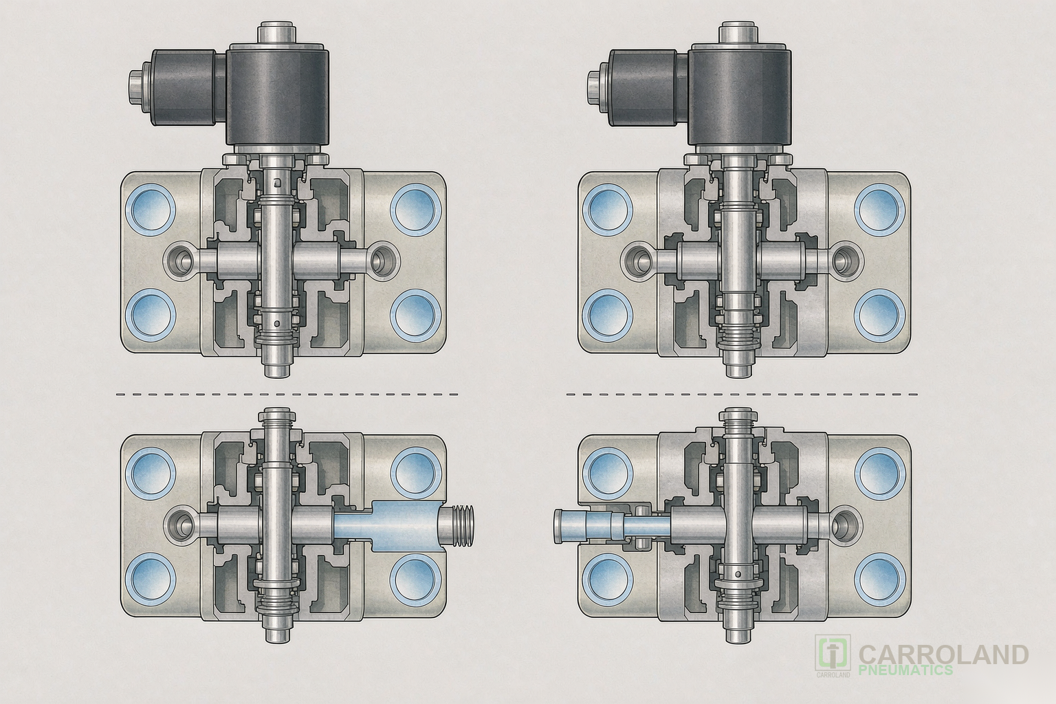
Selecting a directional valve by port count alone is the most common specification error in pneumatic circuits. The port and position notation describes the valve’s construction; the centre position function and the actuation method describe its behaviour. This article separates the two and gives the sequence for specifying a valve that behaves correctly on power loss, For the component-level construction behind these behaviours – coil, armature tube, spool and seals – see our solenoid valve types and working principle guide.
1. Reading the notation
The standard notation describes ports and positions in the form “ports / positions”. The ports are: one pressure supply, two exhausts, and two working ports to the actuator.
| Notation | Meaning | Typical use |
|---|---|---|
| 3/2 | Three ports, two positions | Single-acting cylinders, pilot supply, air blow-off |
| 5/2 | Five ports, two positions | Double-acting cylinders where either end state is acceptable on power loss |
| 5/3 | Five ports, three positions | Double-acting cylinders requiring a defined mid-stroke behaviour |
For solenoid-actuated valves, ISO 5599 covers the mounting interface dimensions, which is what allows a valve to be replaced without reworking the manifold or the tubing. The interface standard covers dimensions, not performance.
2. The three centre positions of a 5/3 valve
Where a 5/3 valve is specified, the centre function must be named explicitly, because the three variants behave in fundamentally different ways when both solenoids are de-energised.
- Closed centre — both working ports are blocked. The cylinder is held by trapped air. Position is retained, but the hold is not absolute: air is compressible and any leakage allows drift under load.
- Exhaust centre — both working ports connect to exhaust. The cylinder is free to move; the load can be shifted by hand. This is the function used where manual repositioning or a free-state stop is required.
- Pressure centre — both working ports connect to supply. Both sides of the piston see supply pressure, and the direction of travel depends on the effective piston areas, which differ because of the rod.
Specifying “5/3” without naming which of these three is required produces a valve that may behave contrary to the safety concept of the machine.
3. Actuation and reset method
The actuation method determines the state the valve returns to when power is removed, and this is the decision that most directly affects machine behaviour on an emergency stop.
| Method | Behaviour on power loss | Where it is used |
|---|---|---|
| Single solenoid, spring reset | Returns to the spring-defined position | Simple two-state motion where a single defined rest state is acceptable |
| Double solenoid | Retains the last commanded position (bistable) | Where the actuator must stay where it was when power is lost |
| Double solenoid with 5/3 centre | Moves to the named centre function | Where a defined mid-stroke state is required on loss of power |
A bistable double-solenoid valve retaining its position is not the same as a safe state. Where the safety concept requires the actuator to move to a defined position on stop, that has to be specified as the valve function, not assumed from the actuation method.
4. Selection sequence
The following order avoids the common failure of choosing a valve by port count and then discovering the behaviour is wrong.
- Define the actuator — single-acting needs 3/2; double-acting needs 5/2 or 5/3.
- Define the required state on power loss — a defined end state suggests spring reset; retaining position suggests bistable double solenoid; a defined mid-stroke state requires a 5/3 with a named centre.
- Name the centre function if a 5/3 is selected — closed, exhaust or pressure — and confirm it matches the safety concept.
- Confirm the mounting interface against ISO 5599 so replacement does not require reworking the manifold.
- Verify the response time against the cycle — switching time is a function of the valve and the load, and it must be checked against the required cycle rate rather than assumed.
Once the valve is fixed, the flow demand it must pass follows from the actuator: our pneumatic cylinder air consumption calculation guide shows how per-cycle demand sizes the valve and the supply line.
5. Frequently asked questions
Can a 5/2 valve replace a 5/3 valve?
Only where the application has no requirement for a defined mid-stroke state. A 5/2 valve has two positions and therefore no centre function; where the safety concept depends on the behaviour of the actuator when both solenoids are off, a 5/3 with a named centre is required.
Does a closed-centre 5/3 valve hold a cylinder securely?
It traps air on both sides, which resists motion, but air is compressible and any leakage permits drift under load. Where a load must be held securely, that requirement has to be met by a mechanical device, not by the valve centre function.
What does ISO 5599 cover?
It covers the mounting interface dimensions for pneumatic directional valves. It standardises the dimensions so that a valve can be replaced without reworking the manifold or tubing; it does not specify or certify performance.
Summary
Specify in this order: actuator type → required state on power loss → centre function where a 5/3 is needed → mounting interface → response against the cycle. The notation tells you what the valve is; the centre function and reset method tell you what it will do, which is what the machine actually depends on.