
Pneumatic Valves and Actuators: Integration Guide for Automation Systems
Industrial buyers frequently group valves actuators under one specification line when sizing pneumatic circuits. A pneumatic valve converts compressed air into mechanical motion; the actuator delivers the force that opens, closes, or modulates the final element. Match the two correctly and the loop runs for years. However, size either half wrong and the plant faces seat wear, stall failures, or torn diaphragms. This guide therefore covers the working principle, common pairings, and the ISO 5211 interface rules that keep control valve pneumatic actuator assemblies interchangeable.
What a Pneumatic Valve Actuator Assembly Actually Does
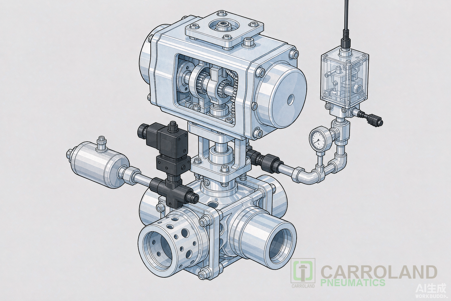
A valve with pneumatic actuator is the final control element in most process lines. The controller sends a signal—usually 4–20 mA or 0.2–1.0 bar (3–15 psi)—to a positioner. The positioner meters air to the actuator housing. The actuator converts that air pressure into linear or rotary motion, driving the plug, disc, or ball to the required position. Air pressure moves the part; spring force or opposite air pressure returns it.
The same logic applies whether the application is a steam control valve with pneumatic actuator in a power plant or a 3 way control valve with pneumatic actuator diverting coolant in an HVAC system. In other words, the difference is only the valve body geometry and the torque or thrust the actuator must produce.
Working Principle: From Signal to Stem Motion
The control loop runs in four stages. First, the PLC or DCS compares the process variable to the setpoint and calculates the required valve position. Second, the positioner converts the controller signal into a proportional air pressure. Third, the air enters the actuator chamber and moves a diaphragm or piston. Finally, the stem transfers that motion to the closure element, changing flow area.
Controller
4-20 mA
Positioner
0.2-1.0 bar
Actuator
Diaphragm/Piston
Valve Stem
Linear / 90°
Flow Modulation
Process Variable
Process Feedback
For a globe control valve with pneumatic actuator, the stem moves linearly. The plug lifts off or presses against the seat, changing the annular flow area. For ball or butterfly valves, a quarter-turn rack-and-pinion or Scotch-yoke actuator rotates the stem 90 degrees. Rotary actuators dominate isolation duty; linear actuators dominate throttling duty.
Actuator Types and Their Valve Pairings
Engineers choose the actuator mechanism by torque profile, not brand. For example, rack-and-pinion units deliver nearly constant torque through the 90-degree sweep. Consequently, that profile suits ball and butterfly valves where dynamic torque stays flat. In contrast, Scotch-yoke units produce a U-shaped torque curve with peak force at the start and end of stroke. As a result, that peak helps break a stuck seat on large valves, so process plants specify Scotch-yoke for high-break-torque duty.
| Actuator Type | Motion | Ideal Valve Body | Torque Profile | Typical Range |
|---|---|---|---|---|
| Rack-and-pinion | Quarter-turn 90° | Ball, butterfly, plug | Constant torque | 10 Nm to 10,000 Nm |
| Scotch-yoke | Quarter-turn 90° | Large ball, high-performance butterfly | Peak at 0° and 90° | 500 Nm to 250,000 Nm |
| Diaphragm linear | Linear | Globe, gate, diaphragm | Force vs. air pressure | Up to 50 kN thrust |
| Piston linear | Linear | Knife gate, large globe | High thrust at high pressure | Up to 200 kN thrust |
Single-acting actuators use a spring to return the valve to a fail-safe position when air pressure drops. Meanwhile, double-acting actuators use air for both directions. Thus, a spring-return actuator valve pneumatic is mandatory for emergency shutdown loops, whereas a double-acting unit is more energy-efficient for frequent cycling.
ISO 5211: The Interface That Makes Replacement Possible
ISO 5211 defines the mechanical handshake between a quarter-turn valve and its actuator. Specifically, the standard covers the flange bolt pattern, the centering spigot, and the stem drive shape. Common flange codes run from F03 to F60. For example, an F03 flange handles up to 32 Nm; an F05 handles up to 125 Nm; an F07 handles up to 250 Nm; an F10 handles up to 1,000 Nm. Larger F14, F16, F25, and F30 flanges carry 2,000 Nm to 32,000 Nm.
The stem drive can be square, double-D, or keyed. Square drives are common on small ball valves. Double-D drives are common on butterfly valves. Keyed drives are required for heavy trunnion-mounted ball valves where stress concentration would round off a square drive. When both valve and actuator carry the same F-code and drive type, they bolt together without custom machining.
For procurement teams, ISO 5211 removes one major integration risk: an actuator from one supplier can mount directly onto a valve from another, provided both share the same F-code. Carroland Pneumatics supplies actuator valve pneumatic packages machined to ISO 5211 tolerances and pairs them with NAMUR accessory mounting per VDI/VDE 3845.
Sizing Rules Every Specifier Should Follow
Start with breakaway torque, not running torque. Because a valve seat that has sat closed over a weekend can require 1.5 times the running torque to crack open, apply a safety factor of 1.25× for clean liquids, 1.5× for dry gases and steam, and up to 2.0× for slurries or high-temperature service. Also, standard plant air pressure is 5.5–8.0 bar (80–116 psi), but size the actuator at the lowest pressure the compressor actually delivers, not the nameplate rating.
Air quality also matters. ISO 8573-1 class 4:4:4 air—solid particles, humidity, and oil each at class 4—is the practical minimum for long actuator life. A 4 2 way directional control valve feeding the actuator must have the same port size and flow coefficient (Cv or Kv) as the actuator ports. Undersized pilot valves slow stroke time and can cause the actuator to hunt.
Solenoid Control Valve and Pilot Logic
A solenoid control valve is the on/off switch that routes air to the actuator. Specifically, a 3/2 solenoid valve drives a single-acting spring-return actuator: one pressure port and one exhaust port. Similarly, a 5/2 solenoid valve drives a double-acting actuator: two pressure ports alternate. The solenoid coil voltage—24 VDC, 110 VAC, or 230 VAC—must therefore match the panel standard.
Mount the solenoid directly on the actuator NAMUR interface when possible. Direct mounting eliminates tubing between pilot and actuator, reduces leak paths, and shortens response time. For manifold systems, a single 4 2 way directional control valve can serve one actuator; valve islands can serve several actuators from one air supply and one electrical connection.
Industry Applications
Pneumatic valve actuators appear wherever speed, safety, or intrinsic explosion protection matters. For instance, in steam lines, a steam control valve with pneumatic actuator modulates temperature by throttling the steam supply; spring-return units fail closed to prevent overheating. In data-center chilled-water loops, quarter-turn rack-and-pinion actuators isolate branches during maintenance and fail closed on loss of air. Meanwhile, in chemical plants, pneumatic actuators avoid electrical ignition sources in Zone 1 and Zone 2 areas.
Food and pharmaceutical lines use stainless actuator housings with tri-clamp valve bodies. Marine applications rely on pneumatic actuators for ballast, fuel oil transfer, and cooling water because compressed air is already available and the units tolerate salt spray better than electric enclosures. The same actuator valve pneumatic package, built to ISO 5211, can span all of these markets with only seal-kit and material changes.
Maintenance and Failure Modes
Three failures account for most field problems. First, contaminated air scores the actuator bore and chews seals. Therefore, install an FRL unit upstream and drain the filter bowl weekly. Second, oversized actuators hammer the valve seat at the end of stroke. Consequently, add travel stops or select an actuator with adjustable cushioning. Third, misalignment between actuator and valve stem creates side load, accelerates bearing wear, and can shear the stem. For this reason, use the ISO 5211 centering spigot and torque the mounting bolts in a cross pattern.
Response time should stay within 1–5 seconds for small-to-medium actuators. Stroke times above that point to an undersized pilot valve, low supply pressure, or a clogged silencer on the exhaust port.
FAQ
What is the difference between a control valve pneumatic actuator and an on/off valve actuator?
A control valve pneumatic actuator receives a modulating signal through a positioner and can hold any intermediate position. An on/off actuator moves only to full open or full closed. The hardware is often identical; the difference is the positioner and the control signal.
Can I mount any ISO 5211 actuator on any ISO 5211 valve?
Yes, if the F-code and drive type match. You must also verify that the actuator output torque exceeds the valve breakaway torque multiplied by the safety factor, and that the valve stem MAST is not lower than the actuator torque.
When should I choose a 3 way control valve with pneumatic actuator?
Use a 3-way valve when you need to divert flow between two paths rather than simply stop it. Common examples include bypass loops, mixing circuits, and coolant diversion in HVAC or machine-tool systems.
Why do steam control valves with pneumatic actuators need larger safety factors?
Steam creates high differential pressure across the seat when the valve is closed. The actuator must produce enough breakaway torque to unseat the plug against that pressure. A 1.5× to 2.0× safety factor is standard for steam.
What is a 4 2 way directional control valve used for?
A 4/2-way directional control valve routes supply air to one side of a double-acting actuator while exhausting the other side. It is the most common pilot valve for double-acting pneumatic actuators in automation systems.
How does a solenoid control valve interface with a pneumatic actuator?
The solenoid valve receives an electrical signal from the PLC and shifts an internal spool. The spool directs compressed air into the actuator port and opens the opposite port to exhaust. Removing the signal returns the spool to its spring-offset position and vents the actuator.
For more detail on pneumatic component selection, see our pneumatic valve and solenoid guide, pneumatic cylinder selection guide, and the Carroland Pneumatics product range. External reference: ISO 5211 mounting dimensions guide.