
Air Grippers: Pneumatic Gripper Types, Selection & Robot Integration Guide
Air grippers convert compressed air into controlled jaw motion, giving automated cells the ability to pick, hold, and place workpieces at cycle times electric drives struggle to match. Engineers specify pneumatic grippers not merely for speed, but for the predictable force curves, clean operation, and compact envelopes that fit dense automation stations. This guide covers the four dominant pneumatic gripper architectures, the force calculations that prevent dropped parts, and the ISO 9409-1 mounting standards that keep robot integration straightforward across brands.
How Air Grippers Convert Air Pressure Into Jaw Motion
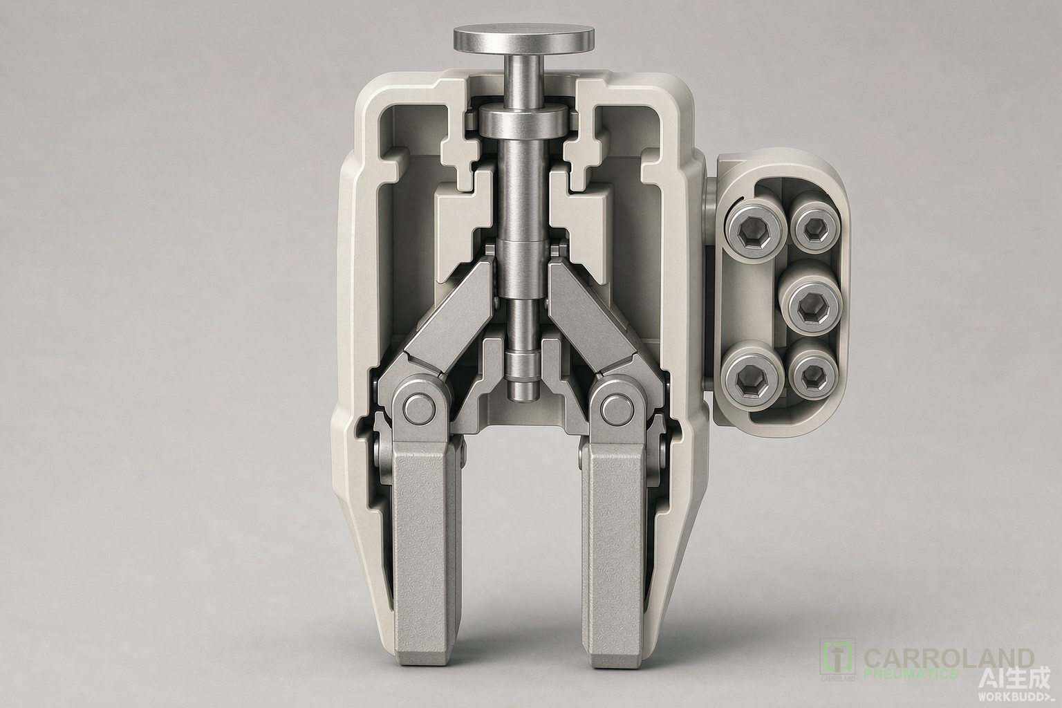
A pneumatic gripper is essentially a double-acting cylinder paired with a mechanical transmission. Compressed air at 0.4–0.7 MPa (4–7 bar) enters one port and pushes a piston. That linear motion becomes jaw travel through one of four internal mechanisms:
- Wedge cam: A tapered pin sits between two roller-equipped jaws. Piston travel pushes the wedge, forcing the jaws apart or allowing springs to close them. Wedge designs deliver high force in compact widths but can develop backlash after millions of cycles.
- Rack-and-pinion: The piston carries a rack that drives a pinion gear. The gear rotates a cam plate, which opens and closes the jaws symmetrically. Rack-and-pinion grippers maintain parallel motion with minimal side load on the guides.
- Linkage lever: A lever system transfers piston force to angular jaws. Lever architectures suit wide-opening angular grippers where fingers must swing clear of fixtures.
- Direct acting: The piston rod connects directly to one jaw; the opposite jaw is spring-returned or driven by a parallel linkage. Direct designs offer the shortest stroke lengths and fastest response.
Most industrial air grippers operate as double-acting units: one air port opens the jaws, the other closes them. Single-acting versions use a spring for the return stroke, providing a default closed or open state when air pressure drops. Double-acting models dominate pick-and-place lines because they deliver consistent grip force in both directions and tolerate pressure fluctuations better than spring-return alternatives. For a deeper look at how double-acting pneumatic cylinders generate force, see our double acting pneumatic cylinder guide.
Four Pneumatic Gripper Types and Their Best Applications
Selecting the wrong jaw motion for a part geometry is the leading cause of intermittent drops and premature wear. The table below compares the four standard architectures found in 2026 manufacturer catalogs.
| Gripper type | Jaw motion | Typical bore range | Best suited for | Critical check point |
|---|---|---|---|---|
| Parallel two-jaw | Linear, opposing paths | 10 mm – 63 mm | Flat or cylindrical parts with repeatable flats | Jaw stroke must cover part width plus finger thickness |
| Angular two-jaw | Arc swing, 10°–30° typical | 16 mm – 50 mm | Confined stations where fingers must clear fixtures | Verify swing arc does not collide with guarding or adjacent tooling |
| Three-jaw centric | Three fingers close toward center at 120° | 20 mm – 80 mm | Round shafts, bushings, bottle necks | Confirm diameter range and equal contact force across all three jaws |
| Wide-opening parallel | Extended linear stroke | 25 mm – 100 mm | Mixed part sizes or long approach clearance | Long fingers increase moment load; check permissible moment ratings |
Parallel two-jaw air grippers account for the largest share of automation orders because most pick-and-place tasks in electronics and light assembly involve boxy or cylindrical parts. Three-jaw units see steady demand from automotive suppliers handling round stock. Angular grippers fit stations where mold cavities or conveyor sides restrict linear jaw travel. Wide-opening models serve palletizing and machine-tending cells that handle multiple SKUs on the same line.
Grip Force Sizing: Why Catalog Values Are Only a Starting Point
Manufacturers publish grip force at a stated pressure and jaw position—usually 0.5 MPa with fingers at the closed stop. That number ignores finger length, part acceleration, surface friction, and pressure drop. A gripper sized around catalog force alone will drop parts when the robot accelerates at 2 g or when shop air dips during compressor cycling.
The calculation starts with the external force trying to move the workpiece. For a part lifted vertically, that force equals mass times gravity plus acceleration. For a 1.2 kg aluminum housing picked at 1.5 g acceleration:
F_external = 1.2 kg × 9.81 m/s² × (1 + 1.5) = 29.4 N
Friction gripping requires the normal force to exceed the external force divided by the coefficient of friction. Dry machined aluminum on steel fingers yields μ ≈ 0.2–0.3. With two contact points and a safety factor of 4:
F_grip_per_jaw = (29.4 N / 0.25) / 2 × 4 = 235 N
At 0.5 MPa supply pressure, the required effective piston area per jaw is roughly 470 mm² before mechanical losses. After accounting for 20–25% linkage friction, the target area rises to approximately 590 mm², which points to a 25 mm–32 mm bore gripper rather than a 16 mm unit that would sit at the edge of its rating.
Oily or powder-coated surfaces can cut the friction coefficient to 0.1 or lower. In those cases, increasing grip force is not the only answer. Serrated jaw inserts, polymer contact pads, or mechanical stops that support the load without relying on friction often deliver more reliable retention than simply moving to a larger bore.
Moment Loads and Finger Design: The Hidden Failure Mode
Every millimeter between the jaw guide and the contact point multiplies the moment applied to the gripper body. A 0.8 kg part held 40 mm from the jaw face generates 31 N·m of bending moment during a 1 g lateral acceleration. If the gripper catalog lists a permissible moment of 20 N·m, the jaw guides will develop play within weeks, destroying repeatability.
Engineers mitigate moment overload through three strategies:
- Shorten fingers: Keep the workpiece center of gravity as close to the jaw face as the part geometry allows.
- Add external supports: Guide rods or bearing rails that carry the part weight independently of the gripper jaws.
- Size for moment, not just force: Select a gripper whose permissible moment rating exceeds the calculated dynamic load by at least 50%.
Custom fingers machined from 6061-T6 aluminum with hardened steel inserts are common in high-cycle cells. Finger mass also matters: heavy fingers increase the inertia the robot must accelerate and can excite vibration during fast transfers. Lightweight aluminum fingers with steel contact pads strike the balance between stiffness and mass.
Robot Integration: ISO 9409-1 and Pneumatic Plumbing
Mounting an air gripper to a robot arm requires more than bolt holes. ISO 9409-1:2004 defines the mechanical interface for circular mounting plates, specifying pitch circle diameters, hole counts, and thread sizes. The most common pattern in collaborative automation is ISO 9409-1-50-4-M6: a 50 mm pitch circle with four M6 threaded holes. Heavy-payload industrial arms often use ISO 9409-1-63-6-M6 or ISO 9409-1-80-6-M8.
Beyond the flange, the integration team must route supply air through the robot wrist or alongside the arm. Internal air passages keep hoses from snagging but limit tubing diameter. External tubing allows larger bores and faster exhaust but requires cable management chains. Double-acting grippers need two air lines; some robot wrists offer four internal passages, leaving two spare lines for vacuum or sensor air.
Speed control valves mounted at the gripper ports—not at the manifold—reduce exhaust back-pressure and give finer cycle-time tuning. Exhaust silencers keep noise below 80 dB in operator-present cells. For clean-room or electronics applications, filtered exhaust ports prevent particulate contamination from the gripper internal mechanism.
Industry Applications for Pneumatic Grippers
Electronics assembly: Parallel jaw grippers with 10 mm–16 mm bores handle PCBs, connectors, and small enclosures at cycle times under 0.8 seconds. Low-contamination models with sealed guides and booted jaws prevent particle generation in Class 1000 environments.
Food and beverage packaging: Three-jaw centric grippers center bottle necks for capping and labeling. Stainless steel bodies and FDA-compliant seals withstand washdown cycles at 60°C. The grippers operate at 0.4–0.5 MPa to avoid crushing thin-walled PET containers.
Automotive machine tending: Wide-opening parallel grippers with 40 mm–63 mm bores move cast brackets and machined housings between CNC stations. Hardened steel guides tolerate metal chip exposure, and double-acting actuation ensures reliable opening even when coolant mist contaminates the exhaust ports.
Pick-and-place robotics: Angular grippers on SCARA arms swing fingers clear of tape feeders and PCB nests during component placement. The compact envelope lets multiple grippers share a single work envelope without interference.
Maintenance and Service Life
A pneumatic gripper rated for 2 million cycles will reach that mark only if the air supply meets ISO 8573-1 Class 4 or better. Water and oil aerosols accelerate seal swelling and guide corrosion. Nitrile rubber (NBR) seals handle standard shop air to 60°C. Fluorocarbon (FKM) seals extend temperature range to 120°C and resist coolant mist in machining cells.
Jaw guide wear manifests as increased backlash. A dial indicator check every 500,000 cycles should show less than 0.05 mm jaw play. Exceeding that tolerance causes part-centering error, which in turn degrades placement accuracy. Rebuild kits typically include piston seals, guide bushings, and wiper rings. Rebuild intervals should match the manufacturer’s recommendation or occur at half the rated cycle life, whichever comes first.
FAQ
What is the difference between a parallel and an angular air gripper?
Parallel air grippers move jaws in straight, opposing lines, keeping finger contact angle constant through the stroke. Angular air grippers pivot jaws through an arc, which clears fixtures in tight spaces but changes contact geometry as the jaws open. Parallel models suit flat or cylindrical parts; angular models fit stations with side-wall obstructions.
How do I calculate the required grip force for a pneumatic gripper?
Multiply the part weight by the acceleration factor (1 + g-force), divide by the coefficient of friction and the number of jaws, then apply a safety factor of 4–6. For a 1 kg part moved at 1.5 g with μ = 0.25 and two jaws, the target grip force per jaw is roughly 120 N before mechanical losses.
Can a pneumatic gripper hold a part if air pressure is lost?
Single-acting grippers with spring-return jaws maintain either an open or closed default state. Double-acting grippers release grip when both ports exhaust. For safety-critical applications, specify a spring-return model or add a mechanical lock that engages when pressure drops below 0.3 MPa.
What ISO standard governs robot gripper mounting?
ISO 9409-1:2004 defines the mechanical interface for mounting end effectors on industrial robots. The designation encodes pitch circle diameter, hole count, and thread size. A common pattern is ISO 9409-1-50-4-M6, indicating a 50 mm pitch circle with four M6 threaded holes.
How long does a pneumatic gripper last in high-cycle automation?
Catalog ratings of 2 million to 5 million cycles assume clean, dry air and loads within the rated force and moment limits. In practice, gripper life drops by 30–50% when operating in coolant mist or with moment loads above 60% of the rated maximum. Rebuild every 1–2 million cycles maintains repeatability.