
Double Acting Pneumatic Cylinder: Selection and Force Guide
A double acting pneumatic cylinder drives the piston in both directions by supplying compressed air alternately to each chamber, so the return stroke produces usable force instead of relying on a spring or external load. This design underpins most industrial automation motion because it delivers controlled thrust on extend and retract, and it scales predictably from small 3C fixtures to heavy clamping stations. The guide below covers working principle, force calculation, component structure, selection rules, and how the actuator fits inside broader pneumatic system components.
How a Double Acting Pneumatic Cylinder Works
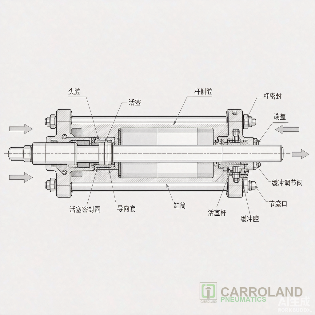
The cylinder body has two air ports. A directional control valve routes compressed air to the cap-end port to extend the rod, then shifts to feed the rod-end port and exhaust the cap end to retract. A 5/2 solenoid valve is the typical control element: its two positions connect one port to pressure while the opposite port vents to atmosphere. Because both strokes are air-powered, the cylinder maintains force throughout the cycle and tolerates vertical or load-reversing applications that a single acting unit cannot.
In a complete circuit pneumatic layout, the actuator sits downstream of the air treatment unit and is sequenced by solenoid valve types selected for flow and response time. The valve’s flow coefficient (Cv or kv) must exceed the cylinder’s demand at the target cycle rate, or the actuator will stall short of full stroke.
Force Calculation at Rated Pressure
Theoretical piston force follows F = p × A, where p is gauge pressure and A is the piston area. Real thrust subtracts seal friction (typically 5–15% of theoretical force). At a standard 6 bar (0.6 MPa) supply, common bore sizes produce the following net figures:
| Bore (mm) | Piston area (cm²) | Theoretical force @ 6 bar (N) | Net force @ 6 bar (N, ~10% friction) |
|---|---|---|---|
| 32 | 8.04 | 483 | ~435 |
| 40 | 12.57 | 754 | ~679 |
| 63 | 31.17 | 1870 | ~1683 |
| 100 | 78.54 | 4712 | ~4241 |
Per ISO 15552:2018 (the harmonized profile-cylinder standard formerly ISO 6431 / VDMA 24562), nominal bores run from 32 mm to 320 mm and the operating envelope is 1–10 bar, with 6 bar treated as the reference condition for catalogue force tables. When the return stroke must pull a load, use the rod-end area (piston area minus rod area), which is always smaller than the cap-end area, so retract force is lower than extend force for a given pressure.
Core Construction of the Actuator
The internal pneumatic air cylinder parts are engineered as a sealed pressure vessel. The tube carries the bore tolerance; the piston divides the two chambers and carries the sealing set; the piston rod transmits thrust and defines the stroke; end caps house the ports and cushioning inserts. Magnetic pistons are common on ISO 15552 units to trigger reed or Hall sensors for end-position feedback without external limit switches.
Cushioning deserves attention: adjustable pneumatic cushions at each end decelerate the piston near stroke limits, cutting impact noise and extending seal life at high cycle rates. For a double acting pneumatic air cylinder running above 1 Hz, omitted or mis-set cushioning is the leading cause of premature seal failure.
Selection Checklist
| Parameter | Rule | Why it matters |
|---|---|---|
| Bore | Size from required force at available pressure | Force scales with area, not diameter linearly |
| Stroke | Match travel + sensor allowance | Oversize stroke adds dead time and cost |
| Mounting | Fixed, foot, flange, or clevis per load geometry | Wrong mount induces side load and rod bending |
| Cushioning | Required above ~1 Hz or heavy mass | Protects seals and reduces noise |
| Speed | Tune with exhaust flow controls | Unmetered flow causes overshoot or stall |
For buyers comparing suppliers, the relevant engineering decision is whether the unit meets ISO 15552 interchange dimensions, not brand lineage. A pneumatic air cylinders double acting cylinder built to the standard drops into existing tooling and accepts standard mounts and sensors regardless of manufacturer.
Where It Sits in the Pneumatic System
The actuator is one node among several pneumatic components. Upstream, the compressor and FRL unit (filter–regulator–lubricator) condition the air to ISO 8573-1 class targets; without clean, regulated supply, the cylinder’s seals and cushions degrade early. Downstream logic and valves shape the motion profile. Treating the actuator as an isolated part misses the fact that 20–30% of compressed-air energy is typically lost to leaks and over-pressure in poorly maintained loops, which inflates the effective cost of every stroke.
Typical Applications
- 3C and electronics automation: clamping, pressing, and pick-and-place where ISO 15552 compact bodies fit tight fixtures.
- Packaging lines: carton pushers and fill gates needing consistent return force.
- Automotive welding and assembly: high-cycle clamping with end-position sensing.
- General pneumatic system components retrofit: replacing single acting units to gain controlled retract.
Maintenance and Common Failures
Most downtime traces to three causes: air contamination scoring the tube, side load from misaligned mounts bending the rod, and exhaust starvation from undersized valves. A scheduled check of filter pressure drop, rod runout, and cushion setting prevents the majority of unplanned stops. Magnetic-position sensors should be verified against actual end travel after any mount change.
Frequently Asked Questions
What is the difference between single acting and double acting pneumatic cylinders?
A single acting unit applies air to one side only; the return stroke uses a spring or external load, so it produces no controlled force on retract. A double acting air cylinder powers both directions, giving usable thrust on extend and retract and supporting load-reversing duty.
How much force does a double acting pneumatic cylinder produce?
Force equals pressure times piston area, minus seal friction. At 6 bar a 63 mm bore yields about 1680 N net; a 100 mm bore about 4240 N net. Use the rod-end area for retract force, which is lower than extend force.
Can a double acting cylinder hold position when air is lost?
Standard units do not lock; both chambers vent and the load can drift. For lock-on-loss safety, specify a locking unit or an external mechanical stop. Do not assume a double acting pneumatic air cylinder holds a suspended load without a brake.
Which standard defines double acting pneumatic cylinder dimensions?
ISO 15552:2018 defines the profile cylinder interface (mounts, rod thread, sensor grooves) so bodies, rods, and brackets are interchangeable across compliant suppliers. Bores span 32–320 mm at 1–10 bar operating pressure.