
Pneumatic Cylinder Parts: OEM Component Guide & Replacement Standards
Pneumatic cylinder parts form the mechanical backbone of every linear actuator in a factory automation line. When a seal fails at 0.8 MPa or a piston rod scores after 2 million cycles, the line stops. Understanding each component—barrel, piston, rod, seals, and end caps—lets engineers specify replacements that restore original performance without redesigning the fixture. This guide breaks down the standard pneumatic cylinder parts you will encounter on ISO 15552 and ISO 6432 units, explains how they interact under pressure, and outlines what to verify when sourcing from a pneumatic cylinder supplier.
1. Pneumatic Cylinder Components: The Six Critical Subsystems
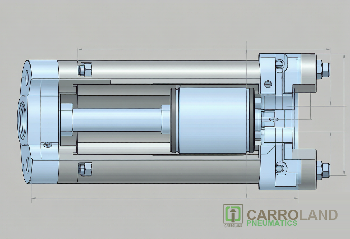
A pneumatic cylinder is not a single casting; it is a pressure-locked assembly of six pneumatic cylinder components that must tolerate cyclic fatigue, seal friction, and side loads. Each part has a material specification, a dimensional tolerance, and a failure mode. Replace one without matching the others, and the unit degrades prematurely.
| Component | Standard Material | Key Spec | Failure Mode |
|---|---|---|---|
| Cylinder Barrel | 6061-T6 aluminum or ST52 steel | ID ±0.02 mm, honed Ra 0.4–0.8 μm | Score marks, ovality from side load |
| Piston | Aluminum or POM | Clearance 0.03–0.05 mm vs barrel ID | Seal groove wear, magnet debonding |
| Piston Rod | AISI 4140 steel, hard chrome plated | Plating 0.05–0.1 mm, Ra 0.2–0.4 μm | Pitting, bending from misalignment |
| Seals (Piston + Rod) | Polyurethane (PU) or NBR | Leakage ≤1 cm³/min at 0.8 MPa | Hardening, extrusion under pressure |
| End Caps (Front/Rear) | ADC12 aluminum or S45C steel | Air port G1/8–G1/2 per ISO 1179 | Crack at cushion screw thread |
| Cushioning / Bumpers | PU elastomer or adjustable needle | Absorb kinetic energy at 0.5 m/s | Compression set, needle erosion |
The barrel is the primary pressure vessel. On ISO 15552 units, it is typically an extruded aluminum profile with four longitudinal sensor slots. On ISO 6432 mini-cylinders, it is a round stainless steel tube crimped at both ends. The inner surface finish matters more than the alloy: a honed barrel with Ra 0.4 μm reduces seal friction by 30–40 % compared to a rough-drawn tube, directly extending the maintenance interval.
2. Pneumatic Cylinder Types: How Component Architecture Drives Form Factor
Not all pneumatic cylinder types share the same internal layout. The standard you select—ISO 15552, ISO 6432, or ISO 21287—dictates barrel geometry, piston diameter, and seal arrangement. Engineers often conflate “cylinder type” with “bore size,” but the architecture itself changes the part list.
2.1 ISO 15552 Profile Cylinders (32–125 mm Bore)
ISO 15552 (formerly ISO 6431 / VDMA 24562) is the default for tie-rod and profile-barrel actuators. The barrel is an extruded square profile with T-slots for magnetic sensors. End caps are bolted with tie rods or threaded studs. Bore sizes run 32, 40, 50, 63, 80, 100, and 125 mm, with strokes up to 1000 mm standard and 2800 mm on request. The component list is fully modular: barrel, piston, rod, seals, and caps can be replaced independently. Operating pressure is 0.04–1.0 MPa, with a proof pressure of 1.5 MPa.
2.2 ISO 6432 Mini Round Cylinders (8–25 mm Bore)
ISO 6432 governs small round-body units. The barrel is a thin-wall stainless steel tube, crimped shut at both ends with non-removable end caps. These air cylinder types are lightweight—roughly 40–50 % of an ISO 15552 unit at the same bore—and are common on pick-and-place heads or robotic grippers. The trade-off is limited repairability: once the crimped seal area is damaged, the barrel assembly is typically replaced as a whole rather than rebuilt from individual air cylinder parts.
2.3 ISO 21287 Compact Cylinders (20–100 mm Bore)
ISO 21287 compact cylinders reduce installation length by roughly 50 % compared to ISO 15552 profiles. They use riveted or C-clip end caps and often omit adjustable air cushions in favor of rubber bumpers. The piston and rod assembly is shorter, which limits stroke length to about 500 mm. Component replacement is possible but requires a snap-ring tool to remove the front cap without deforming the barrel.
3. Single Acting Air Cylinder: Spring-Return Mechanics and Part Differences
A single acting air cylinder changes the internal component list in one critical way: it adds a return spring. In the standard spring-return configuration, compressed air enters the cap-end port to extend the rod, while the spring drives retraction when pressure exhausts. This hybrid energy system introduces a non-linear force curve that double-acting units do not exhibit.
The power stroke must overcome three resistances simultaneously: seal stiction (static friction), the external load, and the spring preload. As the piston extends, the spring compresses according to Hooke’s Law (F = k × x), so the available push force decreases along the stroke. A 50 mm bore cylinder at 0.6 MPa might deliver 1178 N at the start of the stroke but only 1050 N at full extension, depending on the spring rate. Engineers must derate single-acting units by 5–10 % to account for this spring resistance.
The return stroke is uncontrolled by the pneumatic system. The spring force is fixed, and the retraction speed is dictated by the exhaust flow restriction. This makes single acting air cylinder units unsuitable for applications where the return motion must be throttled or carry a heavy load backward. Typical applications are clamps, ejectors, and short-stroke stopper cylinders where the power stroke is the critical motion and the return is merely a reset.
4. Seal Systems: Material Selection and Lifecycle Data
Seals are the most frequently replaced pneumatic cylinder parts, yet they are often the least understood. A piston seal must block cross-chamber leakage (≤1 cm³/min at 0.8 MPa) while keeping breakaway friction low. A rod seal must retain pressure and exclude contaminants. The material choice depends on temperature, speed, and lubrication condition.
| Seal Material | Temperature Range | Max Speed | Best For |
|---|---|---|---|
| NBR (Nitrile) | -20 °C to +80 °C | 0.5 m/s | General factory air, mineral-oil lubrication |
| Polyurethane (PU) | -30 °C to +80 °C | 1.0 m/s | High-speed indexing, low friction |
| FKM (Viton) | -20 °C to +150 °C | 0.5 m/s | Hot environments, chemical exposure |
| PTFE-filled fabric | -40 °C to +200 °C | 1.5 m/s | Food-grade, dry-air, high-speed |
Polyurethane dominates general automation because it combines high tensile strength (≥30 MPa) with excellent abrasion resistance. At speeds above 0.8 m/s, PTFE-filled fabric rings replace U-cups to prevent heat buildup. For food-grade lines, FDA 21 CFR 177.2600 compliant FKM or PTFE seals are mandatory, and lubricants must be NSF H1 registered.
Seal replacement intervals vary by duty cycle. A cylinder cycling 60 times per minute (3,600 cycles/hour) on a double-acting line accumulates roughly 8.6 million cycles per year. Under clean, lubricated conditions, PU seals last 15–20 million cycles. In dusty or unlubricated service, life drops to 5–8 million cycles. The simplest predictive metric is air leakage: if a cylinder begins to creep at rest or the FRL unit shows flow at standstill, the piston seal is bypassing.
5. End Caps, Cushioning, and Porting: Structural Integrity
End caps are the pressure boundaries that seal the barrel and guide the rod. On ISO 15552 units, the rear cap integrates the primary air port (G1/8 to G1/2 per ISO 1179) and may include an adjustable cushion needle. The front cap houses a rod bushing—bronze or PTFE-lined steel—and a wiper seal that scrapes moisture and debris from the rod before it enters the seal zone.
Air cushioning is a wear-reduction feature, not a luxury. Without it, a piston traveling at 0.5 m/s impacts the end cap with kinetic energy proportional to mass and velocity squared. For a 100 mm bore piston with a 10 mm rod, the impact force at the end of a 500 mm stroke can exceed 5000 N. Adjustable cushion needles throttle the exhaust air during the last 20–30 mm of travel, converting kinetic energy into controlled pressure rise. The needle is typically brass or stainless steel, with a fine-pitch thread (M5 × 0.5) for precise flow restriction. Erosion of the needle seat from contaminated air is a common failure; if the cushion becomes ineffective, the end cap suffers repeated hammering and may crack at the mounting bolt bosses.
6. Sourcing Pneumatic Cylinder Parts from a Supplier: Verification Checklist
When you buy replacement pneumatic cylinder parts from a pneumatic cylinder supplier, dimensional compliance is only the first gate. The material certificate, surface finish record, and seal batch test data determine whether the replacement will last 20 million cycles or fail in two weeks. We recommend a five-point verification:
- Barrel ID tolerance: Request a bore gauge report showing ID variation within ±0.02 mm. Ovality above 0.03 mm causes piston bind and uneven seal wear.
- Rod surface hardness: Hard chrome plating should measure HRC 65–72 on the surface. Below HRC 60, the rod scores under dust particles.
- Seal compound certificate: The supplier should provide a Shore-A hardness reading and tensile-strength test for the PU or NBR batch.
- Magnetic piston continuity: If position sensors are used, verify that the piston magnet produces ≥3 mT at the barrel outer surface.
- Pressure test report: Every rebuilt or new assembly should hold 1.5 × rated pressure for 60 seconds without visible leakage or permanent deformation.
Carroland Pneumatics supplies ISO 15552 and ISO 6432 pneumatic cylinder components with full material traceability and batch test reports. Our production lines have served Foxconn-certified iPhone production lines since 2015, where component consistency is measured in parts-per-million defect rates. Learn more about our iPhone production line pneumatic solutions.
7. FAQ
What are the main pneumatic cylinder parts?
The six main parts are the barrel, piston, piston rod, seals (piston and rod), end caps, and cushioning system. Each is standardized under ISO 15552 or ISO 6432 and can be replaced independently on modular profile cylinders.
Can I replace seals without removing the cylinder from the machine?
On tie-rod ISO 15552 cylinders, yes. Remove the tie-rod nuts, pull the front cap, and extract the piston/rod assembly. On crimped ISO 6432 mini-cylinders, seal replacement is impractical; replace the entire barrel assembly.
How do I know if my piston rod chrome plating is worn out?
Run a fingernail across the rod surface. If you feel scoring grooves or see base metal through the chrome, the plating is compromised. A surface roughness gauge should read Ra < 0.4 μm; above 0.8 μm, seal life drops by 50 %.
What is the difference between single acting and double acting pneumatic cylinder parts?
A single acting air cylinder adds an internal return spring and a breather port, but removes the second air port. The end cap geometry differs: the rear cap must house the spring seat and a vent filter to prevent dust ingress during the passive return stroke.
Do pneumatic cylinder parts from different suppliers interchange?
Mounting dimensions (footprint, bolt hole spacing, rod thread) are standardized by ISO 15552 and ISO 6432, so mechanical interchange is guaranteed. However, seal compounds, cushion needle tuning, and sensor slot dimensions vary. Always verify the seal kit part number and sensor bracket geometry before mixing suppliers.