
How a Solenoid Valve Works: The Solenoid Valve Working Principle Explained
Understanding the solenoid valve working principle helps engineers choose the right control element for any automated line. A solenoid valve converts electrical current into a magnetic field that moves a plunger and switches flow. In this guide, we break down solenoid valve working step by step, cover the main construction types, and show how to read a valve symbol.
The Basic Solenoid Valve Working Principle
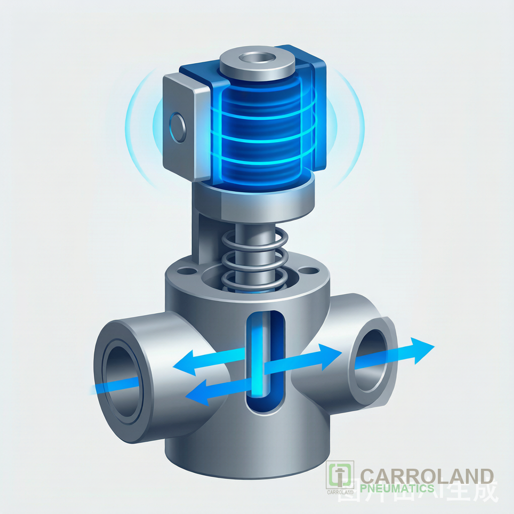
Every solenoid valve has a coil, a plunger (or armature), a spring, and a seat. When current passes through the coil, it becomes an electromagnet. The magnetic pull attracts the plunger and lifts it off the seat, opening the orifice. When current stops, the spring pushes the plunger back and closes the path. Therefore, the electrical signal directly controls fluid flow without manual operation.
Step-by-Step: How a Solenoid Valve Works
The cycle has four clear stages. First, the controller sends voltage to the coil. Then, the coil generates a magnetic field. Next, the field pulls the plunger against the spring. Finally, the orifice opens and medium flows. In reverse, removing power lets the spring reseat the plunger. Specifically, this whole action often completes in under 30 ms on small valves.
Construction Types You Will Meet
Two families dominate. A direct acting valve moves the disc with coil force alone and works at zero pressure. In contrast, a pilot-operated valve uses line pressure to shift a larger main spool, saving coil energy on high flow. Additionally, valves are classed as 2/2, 3/2, or 5/2 by the number of ports and positions. For example, a 5/2 valve directs a double-acting cylinder between two end positions.
Reading the Valve Symbol
A solenoid box on a pneumatic circuit diagram shows the coil as a rhombus or “X” inside a square. The square position indicates the energized state. Consequently, reading the symbol tells you whether the valve is normally closed or normally open at rest. This matters when you size safety-related clamp circuits. Furthermore, the position count (2/2, 5/2, 5/3) tells you how many flow paths the valve manages.
Key Parameters on the Datasheet
| Parameter | What it tells you |
|---|---|
| Way/position (2/2, 5/2…) | Flow path count |
| Orifice and Kv | Maximum flow |
| Pressure range | Operating envelope |
| Coil voltage | Controller match |
| Response time | Cycle-speed limit |
Selection and Maintenance Notes
Choose the valve by voltage, seal material, and flow. First, match the coil to 24 V DC panels. Then select NBR seals for air. Finally, plan preventive maintenance, because dust and moisture shorten coil life. As a result, IP65 enclosures and clean compressed air extend service intervals.
Common Faults and Fixes
A valve that hums but does not shift usually has low supply voltage or a weak spring. Meanwhile, a valve that stays open often has a stuck plunger from contaminated media. Therefore, filtering the air and checking voltage first resolves most field calls.
Pilot Operated Valves in Detail
A pilot operated valve uses a small pilot solenoid to shift a larger main spool with line pressure. Because the pilot only needs to move a tiny element, the main coil can be smaller and cooler. However, the valve cannot shift if line pressure drops below the pilot threshold. Consequently, pilot operated designs suit high-flow supply lines where direct acting would need an oversized coil.
Media, Seals, and Temperature
Air is the common medium, but valves also handle water, oil, and inert gas. For each, the seal decides life: NBR for general air and oil, FKM for heat and chemicals, EPDM for water and steam. In addition, the coil temperature class (for example B, F, H) must exceed the cabinet ambient. Therefore, matching medium and temperature prevents early failure.
Lifecycle and Cycle Count
Quality valves reach tens of millions of cycles. Nevertheless, dirty air and over-voltage shorten that figure. Specifically, adding a 5-micron filter before the valve and regulating voltage within 10% of rating preserves the rated life. As a result, a small upstream investment protects the most switched component on the line.
Frequently Asked Questions
Why does my solenoid valve get hot?
Coils dissipate heat by design. However, continuous duty above rating or a stuck plunger raises temperature. Therefore, match the duty cycle to the application.
What does a clicking sound mean?
A faint click on each switch is normal. Meanwhile, a continuous buzz usually signals low voltage or a weak spring.
What is the difference between 2/2 and 5/2?
A 2/2 valve has one flow path and two states (open/closed). A 5/2 valve switches a double-acting actuator between two ports, so it needs five ports and two positions.
Common Mistakes When Applying the Principle
Engineers often oversize the coil to beat a sticky plunger, when the real cause is dirty air. Similarly, they forget that a 3/2 valve needs an exhaust port, so the cylinder cannot retract. Therefore, start from the working principle, not from a bigger part. As a result, a clean fix beats a costly overspec.
What is a 3/2 valve used for?
A 3/2 valve has three ports and two positions, so it both supplies and exhausts a single-acting actuator. For example, it extends a spring-return cylinder and then vents it.
Do solenoid valves need a filter?
Yes for air. Particles score the seat and cause leaks. A 5-micron filter before the valve is standard on durable lines.
Explore related content: pneumatic valve and solenoid guide and solenoid valve application guide. For cylinder sizing, see our pneumatic cylinder sizing guide.
Standard reference: ISO 15217-1 solenoid actuators.