

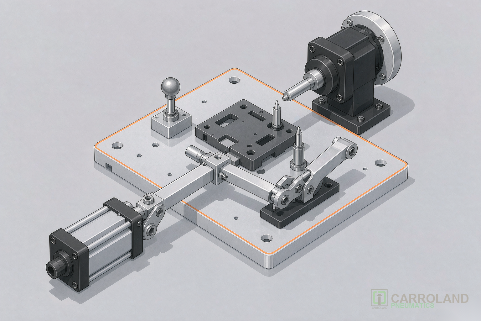
our Pneumatic System for 3C automation: Fixture Design Guide
A pneumatic system for 3C automation drives the clamping, lifting, rotating, and pick-and-place motions that keep smartphone and consumer electronics assembly lines running at cycle times under 3 seconds per unit. Engineers designing these fixture systems face tight constraints. These include compact envelope sizes, repeat positioning accuracy down to plus or minus 0.05 mm, and ESD sensitivity of the workpieces. Cycle counts often exceed 10 million per year. This guide covers component selection, locating principles, air quality requirements, and ESD control measures that determine whether a 3C fixture performs reliably or fails within weeks.
What Defines a 3C automation Pneumatic System
The term “3C” refers to computers, communications, and consumer electronics. This manufacturing sector is dominated by smartphones, tablets, wearables, and PCB assembly. Compared with heavy-industry pneumatics, 3C applications demand smaller bores (16 to 40 mm) and shorter strokes (5 to 20 mm). They also require faster response times and stricter cleanliness standards. A typical smartphone assembly line runs 60 to 120 cycles per minute. Each pneumatic actuator therefore completes 8 to 16 cycles every second across multiple stations.
Three factors set 3C fixture pneumatics apart from general industrial systems. First, the workpieces are fragile. A glass display or bare PCB cannot tolerate the clamping forces used on metal castings. Second, ESD-sensitive components require conductive or static-dissipative materials on every contact surface. Third, the compact footprint of 3C lines leaves little room for oversized cylinders or bulky valve manifolds. Therefore, every component must be sized precisely for both force and space.
Core Components of a Pneumatic Fixture System
A complete pneumatic fixture system for 3C automation integrates five component categories. The table below summarizes their roles and selection criteria.
| Component | Function in Fixture | Key Selection Parameter |
|---|---|---|
| Clamping cylinder | Holds workpiece against locating datum | Grip force 50 to 200 N; repeatability plus or minus 0.05 mm |
| Rotary clamping cylinder | Rotates arm 90 degrees then clamps downward | Zero-stroke option saves vertical space |
| Compact cylinder | Short-stroke actuation in tight envelopes | Bore 16 to 40 mm; stroke 5 to 20 mm |
| Pneumatic gripper | Picks and places parts between stations | Parallel jaw; stroke 3 to 25 mm; force 36 to 160 N |
| Solenoid valve manifold | Directs air to actuators per PLC signals | Flow rate matched to cylinder volume and cycle time |
| FRL air preparation unit | Filters, regulates, and lubricates supply air | ISO 8573-1 class per application requirement |
For a deeper comparison of cylinder types by ISO standard, see our pneumatic cylinder selection guide covering ISO 6432, ISO 15552, and compact profiles. The FRL unit’s role in protecting these components is detailed in our ISO 8573-1 air quality classes guide.
Locating and Clamping Principles for Electronics Fixtures
Fixture design begins with the 3-2-1 locating principle. Three points constrain the primary datum plane, two points constrain the secondary plane, and one point constrains the tertiary plane. Together, these six contact points fully define the workpiece position in all six degrees of freedom. In 3C fixture design, the locating elements are machined to plus or minus 0.01 mm. They are also heat-treated to 55 to 60 HRC for wear resistance over millions of cycles.
Pneumatic System for 3C automation — Fixture Architecture
Air Supply
0.5 to 0.7 MPa
FRL Unit
Filter + Regulator
Valve Manifold
Solenoid 5/2 way
Clamping Cylinder
Pneumatic Gripper
Fixture Workzone
Locating Datum
3-2-1 principle
Workpiece
PCB / Phone part
ESD-Safe
Contact pads
Clamping force must hold the workpiece securely without deforming it. For a typical PCB clamping application, 30 to 80 N per contact point is sufficient. Exceeding this range risks micro-cracking solder joints or flexing thin boards. Rotary clamping cylinders combine a 90-degree swing with downward clamping in a single actuation. This reduces cycle time by eliminating a separate indexing step. The SXL double-force rotary clamping cylinder is a typical example of this category.
Selecting Pneumatic Cylinders for Electronics Manufacturing
Choosing a pneumatic cylinder for electronics manufacturing starts with the force calculation. The basic formula is force equals pressure multiplied by piston area. At 0.5 MPa supply pressure, a 32 mm bore cylinder generates approximately 400 N of theoretical force. After deducting 15 to 20 percent for friction and return spring losses, the net output force lands around 320 to 340 N. This is well above the 50 to 200 N typically needed for 3C clamping.
Stroke length should match the clamping travel with a 2 to 3 mm cushion margin on each end. Overly long strokes waste compressed air and extend cycle time. Strokes that are too short risk bottoming out under tolerance variation. Compact cylinders with bore sizes from 16 to 40 mm and strokes from 5 to 20 mm fit most 3C fixture envelopes. For applications requiring downward clamping after a rotary swing, zero-stroke rotary clamping cylinders eliminate the vertical stroke entirely. This saves up to 40 mm of stack height.
ISO 15552:2018 defines the dimensional interchangeability standard for cylinders with bores from 32 to 320 mm. This standard was confirmed current by ISO in February 2025 after its five-year systematic review. For 3C fixtures, however, compact and miniature cylinders often fit better. These fall outside ISO 15552’s bore range. The selection decision should weigh interchangeability against envelope constraints. Many 3C lines use a mix of both families.
Pneumatic Gripper Integration for Pick-and-Place Operations
Pick-and-place stations transfer parts between conveyor, inspection, and assembly positions. A pneumatic gripper for pick and place applications must deliver consistent jaw positioning across millions of cycles. Parallel grippers with preloaded dual-V roller bearings achieve repeatability of plus or minus 0.01 to 0.03 mm. This is the precision tier required for placing components on PCBs or aligning display modules.
Grip force selection follows a straightforward rule. The gripper must generate at least 5 to 10 times the workpiece weight to account for acceleration forces during transfer. For a 20 g smartphone camera module moving at 1 m per second, a 36 N miniature gripper provides ample margin. The jaw stroke must accommodate the workpiece width plus 1 to 2 mm of clearance for reliable engagement and release.
Air filtration at 40 micron or better is mandatory for gripper longevity. Contaminated air accelerates bearing wear and causes jaw sticking, which directly degrades placement accuracy. For cleanroom-classified 3C lines, grippers equipped with purge or scavenge ports maintain positive internal pressure to prevent particulate ingress. These ports connect to a clean air supply. They are specified in cleanroom environments down to ISO Class 6.
Air Quality and ESD Control in 3C Production
Compressed air quality directly affects fixture reliability. ISO 8573-1 classifies air by solid particle concentration, water content, and oil content. For general 3C fixture applications, Class 3.4.3 is a practical baseline. This means particles up to 5 micron, pressure dew point below 3 degrees Celsius, and oil content under 1 mg per cubic meter. Cleanroom-adjacent stations may require Class 1.2.1 or stricter. That demands a refrigerated or desiccant dryer plus a coalescing filter.
ESD control is equally critical. Electronic components rated to the IEC 61340 standard can be damaged by discharges as low as 100 V. Every pneumatic component that contacts or passes near a workpiece must use static-dissipative materials. This includes gripper fingers, clamping pads, and cylinder rod ends. Conductive elastomers and anodized aluminum with surface resistance below 10 to the 9th ohm per square are the standard ESD-safe choices.
Grounding the fixture base to a common ground point with impedance below 1 ohm prevents charge accumulation on metallic structures. Additionally, ionizing air nozzles at pick-and-place stations neutralize static charges on non-conductive workpieces. Glass displays and plastic housings are treated before the gripper makes contact.
Smartphone Assembly: A Fixture Design Walkthrough
Consider a smartphone mid-frame assembly station that clamps an aluminum chassis for component insertion. The fixture uses four rotary clamping cylinders positioned at the corners. Each generates 120 N of downward clamping force. The locating datum consists of two machined pins (primary and secondary) plus a flat stop (tertiary). This gives full 3-2-1 constraint. Repeat positioning accuracy measures plus or minus 0.05 mm over a 10 million-cycle production run.
The valve manifold controlling these cylinders uses a 5/2-way solenoid valve per actuator, mounted on a common sub-base for compact routing. Supply air passes through an FRL unit set to 0.5 MPa with a 5 micron filter. Cycle time per unit is 2.8 seconds, of which the clamping sequence accounts for 0.4 seconds. This configuration has been validated on iPhone production lines through Foxconn supplier certification. The fixture must maintain dimensional stability across shifts running 20 hours per day.
For OEMs specifying custom fixture systems, the design process moves from requirement definition through CAD modeling to prototype machining and dry-run validation. Suppliers with in-house CNC machining and mold development capabilities can compress this timeline to 4 to 6 weeks. They avoid external machining queue delays that typically add 2 to 3 weeks.
Frequently Asked Questions
What repeatability does a pneumatic system for 3C automation need?
Most 3C fixture applications require repeat positioning accuracy of plus or minus 0.05 mm or better. Precision pick-and-place grippers achieve plus or minus 0.01 to 0.03 mm using preloaded roller bearings. The fixture locating datum itself should be machined to plus or minus 0.01 mm. This avoids introducing error at the mechanical interface.
Which air quality class is recommended for electronics manufacturing fixtures?
ISO 8573-1 Class 3.4.3 is a practical baseline for general 3C fixture stations. Cleanroom-classified areas handling bare PCBs or semiconductors require Class 1.2.1 or stricter. That demands desiccant drying and coalescing filtration. Installing a properly sized FRL unit at each station maintains the target class consistently.
How long do pneumatic grippers last in high-cycle 3C production?
Quality parallel grippers rated for 5 million cycles typically last 10 million or more with scheduled seal replacement and proper air filtration. At 60 cycles per minute over a 20-hour daily shift, a gripper accumulates approximately 72,000 cycles per day. It reaches 5 million cycles in about 70 production days. Preventive seal kit replacement every 3 to 4 months extends service life significantly.
Can compact cylinders replace ISO 15552 cylinders in 3C fixtures?
Yes, in many cases. Compact cylinders with bores from 16 to 40 mm fit the tight envelopes typical of 3C lines better than ISO 15552 cylinders. ISO 15552 cylinders start at 32 mm bore and carry larger mounting footprints. The trade-off is interchangeability. ISO 15552 cylinders offer cross-brand dimensional compatibility, while compact cylinders are often brand-specific. Many 3C lines use both families strategically.