
Pneumatic Valve Parts: Solenoid Coil, Spool and Seal Guide
Pneumatic valve parts are the individual components inside a directional control valve. They include the body, the spool or poppet, the seal stack, the return spring and the solenoid operator. Together they decide how the valve shifts and how tightly it seals in an industrial compressed air circuit. Maintenance teams rarely replace a whole valve. They replace the one part that failed. Component-level knowledge shortens downtime, because each failure mode points somewhere else. A leaking seal stack, a burnt coil and a stuck spool point to three different root causes. Each one calls for a different spare and a different service interval.
This guide covers the anatomy of a directional valve and the way engineers specify each part. It also covers the failure patterns that repeat on high-cycle production lines.
How a Directional Control Valve Shifts Air
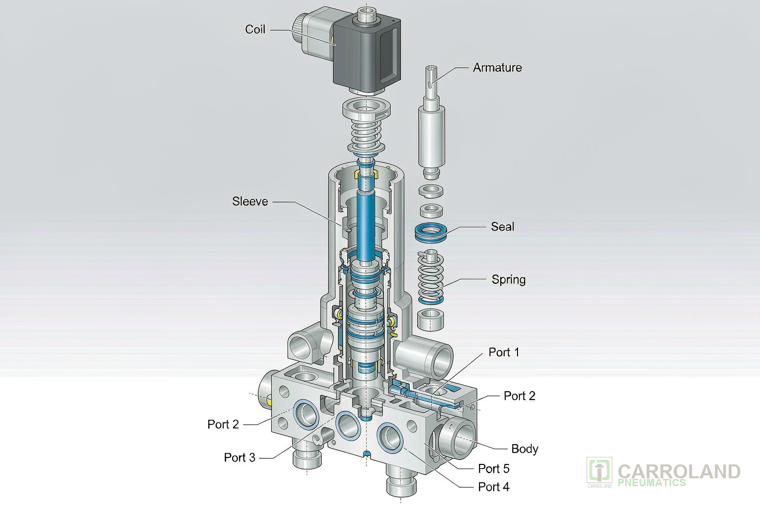
A directional control valve is a fluid-power device that routes supply air to one or more actuator ports. These valves sit in circuits that extend, retract or hold a cylinder position. Inside the valve, a moving element blocks and opens internal passages as it travels. The supply enters at port 1 and the working lines leave at ports 2 and 4. Exhaust leaves at ports 3 and 5.
Two designs dominate industrial air circuits, and the choice drives every spare part downstream.
A spool and sleeve valve slides a hardened, lapped spool through a matched sleeve. The diametrical clearance between the two forms the seal, so no elastomer sits in the main air path. This design tolerates very high cycle counts. It also works from vacuum up to the rated pressure and stays reliable on dry, non-lubricated air. It is the default for high-cycle automation.
A poppet valve presses an elastomer-faced disc onto a seat. It gives a tighter shut-off and resists contamination better than a spool. That is because no close clearance exists to jam. It needs a minimum inlet pressure to re-seat cleanly. So it suits manifold blocks and pilot circuits rather than vacuum duty.
Port naming follows one rule. The first digit counts working ports and the second counts positions. A 5/2 valve feeds two actuator ports from one supply and vents the unused port to exhaust. A 3/2 valve serves a single acting cylinder or a pilot line. Once you know the function code, the internal parts are predictable.
graph LR
  A["Supply port 1"] --> B["Spool in sleeve"]
  B --> C["Working port 2"]
  B --> D["Working port 4"]
  C --> E["Extend chamber"]
  D --> F["Retract chamber"]
  C --> G["Exhaust port 3"]
  D --> H["Exhaust port 5"]
  I["Solenoid coil"] --> J["Armature"] --> B
Solenoid Valve Components: Coil, Armature and Seal Stack
Solenoid valve components are the load-bearing parts that convert an electrical signal into mechanical spool movement. They are used in pilot-operated valves, where a small coil must shift a larger spool. Four of them account for most field failures, and each one fails in a different way.
- Coil — the magnet wire winding. It fails through insulation breakdown after overheating, or through an open circuit after moisture ingress at the connector.
- Armature (plunger) — the movable core that the coil pulls. It sticks when airborne oil varnish builds on the tube, and it wears at the seating face after long cycling.
- Shading ring — a copper ring set into the armature face. It keeps an alternating-current armature from chattering at twice line frequency. A cracked ring produces a loud buzz and slow shifting.
- Seal stack — the O-rings, lip seals and bonded seat discs that separate the electromagnetic chamber from line pressure. It is the part that most often causes external leakage.
Manual override sits on the same assembly. A screw-type override lets a technician shift the valve without energising the coil. That is useful during commissioning and fault finding. A covered or flush override prevents accidental actuation.
Solenoid Coil Types, Voltage Classes and Duty Cycle
A solenoid coil is an inductive winding that turns current and turn count into magnetic flux. The flux pulls the armature against the combined force of the return spring and line pressure. Coil specification starts with the supply. Direct current coils, most often 24 V DC, produce a steady holding force. Alternating current coils are commonly 110/120 V AC or 230/240 V AC. They draw a high inrush current, then settle to a lower holding current.
Two numbers govern thermal life. Insulation class F permits a winding hotspot of 155 °C, and class H permits 180 °C. A coil run above its class temperature loses dielectric strength quickly. So the ambient temperature at the manifold decides the class, not the catalogue price.
Duty cycle is the second limit. A valve coil rated for continuous duty can stay energised without a cooling interval. The nameplate states the permitted on-time. An intermittent rating assumes the coil cools between operations, so it suits only short, spaced cycles. Fitting an intermittent coil to a continuously energised line is a common cause of premature failure.
Check three details before ordering any replacement valve coil: rated voltage and frequency, connector form, and bore diameter. The bore diameter and tube length must match the existing armature. A coil that fits the tube but uses a different connector body wastes a service visit.
Spool, Sleeve and Seal Materials
Seal materials in a pneumatic valve are elastomeric compounds selected for chemical compatibility, temperature range and wear behaviour. They are used where a spool or poppet must close against a seat without leaking. Material choice follows the medium and the ambient temperature rather than the unit cost. Published elastomer datasheets give the service windows below.
| Seal material | Typical service window | Preferred duty | Limitation |
|---|---|---|---|
| Nitrile (NBR) | about −20 °C to +80 °C | General industrial air, lubricated or dry | Swells in aromatic and ketone solvents |
| Fluorocarbon (FKM) | up to about +105 °C | High ambient, aggressive compressor oils | Higher cost, poor with some phosphate esters |
| Ethylene propylene (EPDM) | wide water and steam range | Water, steam, brake fluid circuits | Poor resistance to mineral oil |
| Polytetrafluoroethylene (PTFE) | about −60 °C to +200 °C | Chemical duty, low-friction sealing | Low elasticity, needs a spring energiser |
Body and spool materials follow the same logic. Aluminium bodies keep mass low and suit die-cast manifolds. Hard-anodised aluminium resists wear at the spool land. Stainless steel suits wash-down, food contact and corrosive atmospheres, at higher cost and weight.
Surface finish matters as much as material. On a spool valve, the clearance between spool and sleeve forms the seal. A scored land from contaminated air therefore leaks internally and drops actuator speed before any external leak appears. Filtration upstream protects that clearance more effectively than any seal upgrade.
Pneumatic Piston Valve and Double Acting Pneumatic Valve Circuits
A pneumatic piston valve is a poppet-and-piston assembly that isolates the solenoid chamber from line pressure. It is used in compact 3/2 and 5/2 circuits, where the operator must fit inside a manifold. Line pressure acts on a small piston, and the piston moves the main seal. Because the coil only has to move a light armature against a small pilot force, the solenoid stays small. The valve therefore shifts reliably at low power.
A double acting pneumatic valve circuit mounts one 5/2 valve per cylinder. The valve feeds port 2 while venting port 4, and reverses that pattern on the opposite signal. Two centre conditions are available on a 5/3 version. A closed centre traps both lines and holds the piston in position. An exhaust centre releases both lines so the load can float.
Pilot supply is the detail that catches retrofit projects. An internal pilot draws its pilot air from the valve inlet. So it fails to shift below a minimum inlet pressure. An external pilot draws from a separate line. So it holds position even when the main supply falls away. Specify external pilot for low-pressure or vacuum duty.
Industrial Solenoid Valve Interfaces: ISO 5599-1 Sub-bases and ISO 1179 Ports
Sub-base interfaces are the mounting faces that fix port positions and bolt pattern. They are used to mount valves of the same size without re-piping the manifold. ISO 5599-1 defines four interface sizes with nominal port threads. Size 1 is G1/4, size 2 is G3/8, size 3 is G1/2 and size 4 is G3/4. A valve body aligned with ISO 5599-1 size 2 mounts on any matching size 2 sub-base. A plant can then hold one spare body, rather than a proprietary variant for each machine.
An industrial solenoid valve bolted to a sub-base gains three practical advantages. The piping stays fixed while the valve is swapped. A gang manifold shares a single supply and exhaust passage across several stations. That cuts external fittings. Interposed flow controls sit between body and base and give each actuator port its own speed setting.
Port threads on the sub-base and the fittings follow ISO 1179. That standard specifies G-thread stud ends with an elastomeric seal. Matching thread form and seal type prevents a weeping joint. Such a joint appears when a tapered thread is forced into a parallel port.
System safety forms a separate layer. ISO 4414 sets the requirements for pneumatic fluid power systems. Those requirements cover safe exhaust of trapped air, protection against unexpected start-up and guarding of moving actuators. Design vocabulary follows ISO 5598. Both belong in the specification package alongside the dimensional drawings.
Solenoid Valve Assembly, Air Quality and Replacement
Valve maintenance is the practice of replacing wear parts before leakage degrades cycle time and air consumption. It is used in plants that track compressed air cost per production line. The solenoid valve assembly itself is short. The assembly runs from the retaining nut, coil and armature tube. It continues through the spool, seal stack and return spring. The body and end caps complete the stack. Most field work touches the coil, the armature tube, the spool and the seal stack.
Compressed Air Quality Classes and Valve Life
Compressed air quality sets how often those parts are needed. ISO 8573-1:2010 classifies compressed air by particle, water and oil content. Class 2 caps water at a pressure dew point of −40 °C and total oil at 0.1 mg/m³. The next class down, class 3, allows −20 °C and 1 mg/m³. Class 4 allows +3 °C and 5 mg/m³. For valve reliability the particle class matters most. Class 3 permits up to 90,000 particles per cubic metre in the 0.5 to 1.0 µm band. Class 4 permits up to 10,000 in the 1.0 to 5.0 µm band.
Water that condenses in a cold line washes lubricant from a spool and corrodes carbon steel springs. Oil carried over from the compressor forms varnish on the armature tube and causes sticking. Specify air treatment to the class the valve needs. Then verify it at the point of use with a dew point meter and a particle counter. Upstream filtration equipment is covered in the guide to ISO 8573-1 air quality classes for FRL selection.
Replacement procedure follows five steps. Isolate the valve, exhaust the trapped air and lock out the supply. Then swap the worn part with the coil de-energised, and record the failure mode. Recording the mode is what turns a spare-part habit into a maintenance plan.
The numbering used across a valve range is set out in the overview of pneumatic valve types and working principle. Component drawings are collected there too. Where a valve body is replaced rather than repaired, the part-number logic applies in the same way. It is set out in the OEM pneumatic component guide.
Carroland supplies pneumatic cylinders, valves and air preparation units for OEM and export programmes.
Frequently Asked Questions
What are the main pneumatic valve parts?
The main parts are the body, the spool or poppet, the seal stack and the return spring. The armature and the solenoid coil complete the assembly. A pilot-operated valve adds a pilot piston. On a 5/2 valve the spool is the moving element. It connects the supply to one working port while venting the other.
How do I tell whether a solenoid coil or a spool is faulty?
Measure coil resistance against the rated value. An open circuit points to the coil. If the coil is sound, energise the valve and listen. A dull click with no air shift indicates a stuck spool or a swollen seal. A loud buzz usually points to a cracked shading ring in an alternating-current coil.
Which seal material should I choose for a high-temperature line?
Fluorocarbon (FKM) seals handle ambient conditions up to about +105 °C. Nitrile (NBR) suits general duty up to about +80 °C. Check the compressor oil as well as the ambient temperature. Some synthetic oils attack nitrile even inside its temperature window.
What do the numbers 5/2 and 3/2 mean on a valve?
The first digit gives the number of working ports and the second gives the number of positions. A 5/2 valve controls a double acting cylinder. A 3/2 valve controls a single acting cylinder or a pilot signal line.
What air quality class protects a solenoid valve best?
In most industrial plants the target is ISO 8573-1 class 2:4:2 or better. Water class 4 at +3 °C pressure dew point suits indoor lines. A particle class of 2 or 3 protects the spool clearance. Where the valve sits in a cold or outdoor line, move the water class to 3. That prevents condensation, since class 3 holds −20 °C.