
Double Acting Pneumatic Cylinder: Working Principle and Selection Guide
A double acting pneumatic piston — the industry term most engineers recognize as a double acting pneumatic cylinder — delivers controlled linear force in both extension and retraction strokes. Unlike single acting designs that rely on a return spring, the double acting configuration applies compressed air alternately to each side of the piston, producing thrust in both directions. This makes it the default choice for automation lines requiring bidirectional load handling, precise positioning, and cycle rates above 60 strokes per minute.
At Carroland Pneumatics, we machine ISO 15552 profile cylinders and ISO 6432 round cylinders with bore sizes from 8 mm to 125 mm, supplying automation builders and OEMs across 3C electronics, automotive, and packaging sectors. Our iPhone production line pneumatic solutions rely on double acting cylinders for clamping, ejection, and transfer motions that must repeat within ±0.1 mm across millions of cycles.
What Is a Double Acting Pneumatic Piston?
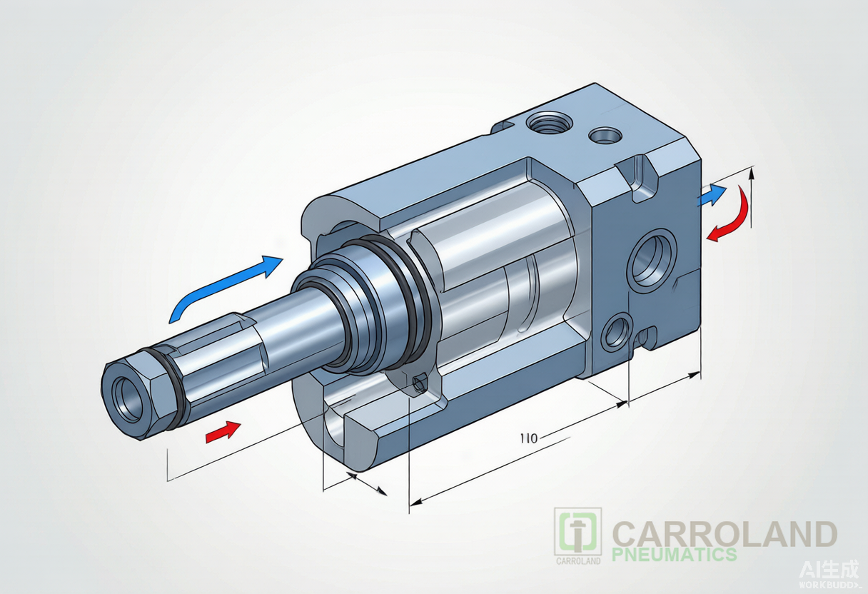
A double acting pneumatic piston consists of a cylindrical barrel, a piston with circumferential seals, a hardened piston rod, and end caps that contain air ports and cushioning mechanisms. Compressed air enters through one port to push the piston forward; exhaust vents through the opposite port. Reversing the air path drives the piston back. Because both strokes are pneumatically powered, the actuator generates independent thrust values for extension and retraction.
The key structural elements include:
- Barrel: Precision-honed aluminum alloy or stainless steel tube with surface roughness Ra 0.4–0.8 µm to minimize seal wear.
- Piston: Aluminum or composite disc carrying NBR, PU, or Viton seals depending on temperature and media.
- Piston rod: Hard-chrome-plated carbon steel (typically Ø 12–40 mm) or 304 stainless steel for corrosive environments.
- End caps: Cast aluminum or engineered polymer, integrating G1/8 to G1/2 air ports, adjustable cushion needles, and rod bushings.
- Magnetic ring: Optional ferrite or NdFeB ring embedded in the piston for reed-switch or Hall-sensor position feedback.
How Double Acting Pneumatic Cylinders Work
The operating cycle divides into four phases: extend, extend cushion, retract, and retract cushion. During extension, compressed air at supply pressure (typically 0.4–0.6 MPa) fills the cap-end chamber (the side opposite the rod). The resulting pressure differential across the full piston area produces thrust. Exhaust air from the rod-end chamber exits through the control valve and silencer.
Approximately 5–10 mm before the mechanical end of stroke, a tapered cushion plunger on the piston enters a matching bore in the end cap. The exhaust path narrows, creating back-pressure that decelerates the piston mass. Engineers adjust cushion needles to set deceleration rates between 100 mm/s² and 5,000 mm/s², preventing impact damage and reducing noise by 8–12 dB compared with uncushioned stops.
During retraction, air flows to the rod-end chamber. Because the piston rod occupies part of this chamber, the effective pressure area is smaller than the cap-end area. Consequently, the retract thrust is 15–30% lower than the extend thrust for the same supply pressure. This asymmetry is predictable and must be accounted for when sizing cylinders for push-pull applications such as gate actuation or shuttle transfer.
Force Calculation for Double Acting Cylinders
The theoretical output force follows Pascal’s law: F = P × A, where F is force in Newtons, P is gauge pressure in Pascals, and A is the effective piston area in square metres. For practical shop-floor calculations at 6 bar (0.6 MPa), engineers use the simplified formula:
F_extend (N) = 0.471 × D² where D is bore diameter in millimetres.
F_retract (N) = 0.471 × (D² – d²) where d is piston rod diameter in millimetres.
The table below lists theoretical thrust and pull forces for standard ISO 15552 double acting pneumatic cylinders at 6 bar, based on ISO 15552:2018 dimensional conventions:
| Bore (mm) | Rod Ø (mm) | Thrust Force (N) | Pull Force (N) | Force Ratio |
|---|---|---|---|---|
| 32 | 12 | 483 | 415 | 1.16 |
| 40 | 16 | 754 | 633 | 1.19 |
| 50 | 20 | 1,178 | 990 | 1.19 |
| 63 | 20 | 1,870 | 1,682 | 1.11 |
| 80 | 25 | 3,016 | 2,721 | 1.11 |
| 100 | 25 | 4,712 | 4,418 | 1.07 |
Real-world output is lower due to friction, seal drag, and back-pressure. A safety factor of 1.5–2.0 is standard practice. For example, if an application requires 800 N retract force, a 50 mm bore cylinder at 6 bar delivers 990 N theoretically; applying a 1.5 safety factor yields 660 N effective capacity, which is insufficient. The next size, 63 mm bore, provides 1,682 N theoretical or approximately 1,121 N effective — the correct choice. For a complete bore-to-force walkthrough with worked examples at 0.4–0.8 MPa supply pressure, see our pneumatic cylinder sizing and force calculation guide.
Single Acting vs Double Acting: Key Differences
Choosing between a single acting actuator and a double acting pneumatic piston depends on force direction, cycle rate, and fail-safe requirements. The table below summarizes the engineering trade-offs:
| Feature | Single Acting Cylinder | Double Acting Cylinder |
|---|---|---|
| Air ports | 1 (single inlet) | 2 (extend and retract) |
| Return mechanism | Internal spring or external load | Compressed air on rod side |
| Force direction | One direction only | Both directions |
| Air consumption per cycle | ~40–50% lower | Higher (both chambers fed) |
| Control valve | 3/2-way | 4/2-way or 5/2-way |
| Cycle speed | Moderate (spring-limited) | Faster (air-driven return) |
| Stroke ceiling | ~300 mm (spring envelope) | Up to 2,000 mm+ |
| Mid-stroke hold | Not possible | Possible with 5/3-way valve |
| Typical applications | Clamping, marking, ejection | Pressing, conveying, robotics |
Single acting designs suit applications where work occurs in one direction and gravity or an external spring handles return. They consume less air and pair with simpler 3/2 solenoid valves, cutting valve and piping costs by roughly 30%. However, spring fatigue limits cycle life to 2–5 million strokes in contaminated environments, and bore sizes above 63 mm become impractical due to spring bulk.
Double acting pneumatic cylinders dominate high-cycle automation. A 5/2 directional control valve switches air paths within 15–30 ms, enabling cycle rates above 120 strokes per minute on short-stroke units. The absence of a return spring also eliminates spring-force opposition, so a 40 mm bore double acting cylinder at 0.5 MPa delivers approximately 15–20% more effective push force than a single acting equivalent of the same bore and pressure.
Round Cylinder vs Profile Cylinder
Within the double acting category, engineers must choose between round cylinder and profile (tie-rod) constructions. A round cylinder features a seamless aluminum barrel with integral mounting threads, offering smooth external surfaces ideal for food-grade or clean-room environments. ISO 6432 defines round mini cylinders from 8 mm to 25 mm bore; ISO 21287 covers compact round designs from 20 mm to 100 mm.
Profile cylinders, standardized under ISO 15552, use extruded aluminum barrels with longitudinal T-slots for sensor mounting and tie rods that clamp the end caps. The T-slot system accepts M4 or M5 slot nuts, allowing proximity switches and cable carriers to attach without bracketry. Profile cylinders withstand higher side loads because the tie-rod structure resists barrel ovalization under pressure spikes up to 1.0 MPa.
For 3C automation fixtures where space is constrained and weight must be minimized, round compact cylinders with 16–32 mm bore and 10–50 mm stroke are typical. For automotive welding jigs and conveyor pushers, ISO 15552 profile cylinders in 50–100 mm bore provide the rigidity and sensor integration that long-term reliability demands.
ISO Standards and Dimensional Interchangeability
ISO 15552:2018 (formerly ISO 6431) governs the dimensions, tolerances, and test methods for profile double acting pneumatic cylinders from 32 mm to 320 mm bore. The standard specifies:
- Mounting hole patterns for foot, flange, clevis, and trunnion styles.
- Port thread sizes: G1/8 for 32 mm, G1/4 for 40–63 mm, G3/8 for 80–100 mm.
- Stroke tolerance: ±2 mm for strokes up to 500 mm, ±1% for longer strokes.
- Leakage rate: ≤ 15 cm³/h at 0.63 MPa with the piston at mid-stroke.
ISO 15552 compliance guarantees dimensional interchangeability across manufacturers. A 50 mm bore × 100 mm stroke cylinder from Carroland mounts on the same bolt pattern as any other ISO 15552-compliant unit, reducing spare-inventory complexity for plant engineers. For a complete reference table of bore, stroke, rod, port-thread and mounting tolerances per ISO 15552:2018, see our ISO 15552 dimensional reference guide.
ISO 6432:2023 covers round mini cylinders from 8 mm to 25 mm bore. These units use M5 × 0.8 or G1/8 ports and feature non-repairable sealed constructions in many commercial variants. For repairable versions, the standard defines piston-rod runout tolerance of ≤ 0.05 mm per 100 mm stroke, ensuring consistent seal life.
Industry Applications
Double acting pneumatic cylinders serve as the primary motion source in automated assembly, material handling, and test equipment. Specific sectors include:
- 3C electronics assembly: Pick-and-place modules use 16–25 mm bore compact double acting cylinders for component insertion forces of 20–80 N at cycle rates of 90–120 per minute. Foxconn-certified suppliers for iPhone production lines specify ISO 21287 compact cylinders with stainless-steel rods and PTFE-impregnated seals to meet clean-room Class 1000 requirements.
- Automotive body-in-white: Welding fixture clamps employ 63–100 mm bore profile cylinders to generate 1,500–4,500 N clamping force. Magnetic position switches confirm clamp-closed status before the weld controller energizes.
- Food and beverage packaging: Stainless-steel round cylinders with FDA-compliant seals handle carton erecting and sealing at 0.4 MPa in washdown environments. The smooth barrel surface simplifies CIP (clean-in-place) procedures.
- Textile machinery: Yarn tensioners and selvedge tuckers use 20–32 mm bore double acting cylinders with low-friction seals to maintain ±2 cN tension stability across 8-hour shifts.
Global demand for pneumatic actuators continues to expand. Industry analysis projects the pneumatic cylinder market to grow from USD 13.4 billion in 2025 to USD 18.8 billion by 2032, at a CAGR of 4.92%. Double acting designs account for over 62% of unit volume in industrial automation, driven by Industry 4.0 investments in Asia-Pacific and Eastern Europe.
Maintenance and Troubleshooting
Predictive maintenance for double acting pneumatic cylinders focuses on three failure modes: seal degradation, rod corrosion, and cushion erosion. NBR seals typically last 3–5 million cycles at 0.6 MPa and 20°C; polyurethane seals extend this to 8–12 million cycles under clean, lubricated conditions. Temperatures above 80°C accelerate nitrile hardening, reducing seal life by 50% for every 10°C increase beyond the rated limit.
Rod corrosion appears first as surface pitting within 6–12 months in humid or chemically aggressive atmospheres. Switching to 316 stainless steel rods or adding polymer wiper rings extends rod life by 3–4×. Cushion needle erosion, caused by particulate matter in exhaust air, produces uneven deceleration and end-cap impact. Replacing standard steel needles with hardened stainless inserts and installing 5 µm coalescing filters upstream of the valve manifold eliminates this mode.
FAQ
What is the main advantage of a double acting pneumatic piston over a single acting design?
The double acting configuration produces powered thrust in both extension and retraction, enabling longer strokes, higher cycle rates, and bidirectional load control. It also supports mid-stroke positioning when paired with a 5/3-way closed-center valve.
How do I calculate the correct bore size for a double acting cylinder?
Divide the required working force by the available pressure and a safety factor of 1.5–2.0. For example, 1,000 N at 0.6 MPa with a 1.5 safety factor needs a theoretical output of 1,500 N. A 63 mm bore cylinder delivers 1,870 N at 6 bar, satisfying the requirement.
Why is retract force lower than extend force in a double acting cylinder?
The piston rod reduces the effective pressure area on the rod side. For a 50 mm bore with 20 mm rod, the retract area is 70.7% of the extend area, so retract force at the same pressure is approximately 84% of extend force.
Can I use a double acting cylinder in a vertical orientation with gravity assisting return?
Yes, but size the retract stroke for the load weight plus friction. If the load exceeds the available retract force, add a counterbalance valve or upsize the bore. Single acting cylinders are often simpler for gravity-return vertical applications.
What is the difference between a round cylinder and a profile cylinder?
A round cylinder has a smooth cylindrical barrel, ideal for clean environments and compact spaces. A profile cylinder uses an extruded barrel with T-slots and tie rods, offering stronger construction, easier sensor mounting, and compliance with ISO 15552 for bore sizes 32 mm and above.