
When installation length, side-load tolerance, or contamination resistance decides the actuator choice, the rodless pneumatic cylinder moves to the top of the spec sheet. Unlike a standard tie-rod cylinder whose total envelope equals roughly twice the stroke, a rodless design collapses the carriage and piston into a single housing. In practice, that saves 50% of mounting space on horizontal transfer lines and gives packaging, automotive, and electronics OEMs a path to denser automation cells.
This guide walks an engineer through the selection logic for a rodless pneumatic cylinder in 2026. Specifically, it covers the working principle, the three drive variants (magnetic coupling, band, cable), and mounting choices under ISO 15552:2018 (re-confirmed 2025-02-04 at stage 90.93) and ISO 21287 for compact profiles. It also reviews force and cushion sizing, and the application fit in packaging, automotive, and electronics lines.
Why engineers move from rod cylinders to rodless pneumatic cylinder designs
The decision to upgrade from a standard ISO 15552 tie-rod cylinder to a rodless pneumatic cylinder is rarely about thrust. Both styles share the same 1,000 kPa (10 bar) maximum working pressure defined in ISO 15552:2018 and the same bore increments (32 mm to 320 mm). However, the decision is driven by three physical constraints a rod cylinder cannot solve:
- Space envelope. A 1,000 mm stroke on a rod cylinder requires roughly 2,000 mm of clearance to let the rod extend without hitting a fixture. A rodless pneumatic cylinder of the same stroke needs only the housing length plus about 30 mm for end caps. Field data from packaging OEMs confirms installation-length savings close to 50% in the 25–80 mm bore range.
- Side-load capacity. A rod cylinder side-loaded by more than a few percent of its thrust develops premature rod-bearing wear. For example, even a 1° misalignment raises internal friction by 25%. Rodless designs route the load through an integral carriage and guide rail. They distribute the force across linear bearings and absorb 40–60% of thrust as a rated side load without damage.
- Contamination and cleanliness. A magnetic-coupling rodless pneumatic cylinder has no slot in the barrel — the piston and carriage couple through a sealed tube wall. In washdown, food-grade, or class-7 cleanroom lines, this closed design eliminates the lubricant wicking that a band cylinder allows at its longitudinal slot. See our ISO 8573-1 air quality guide for the upstream filtration requirements.
For these reasons, packaging OEMs running 10,000+ cycles/day on form-fill-seal machines, automotive tier-1s pressing panels in tight weld cells, and electronics assemblers handling PCBA trays now standardize on rodless pneumatic cylinder variants. Therefore, the rest of this guide focuses on the engineering trade-offs between the three drive families.
Working principle: how a rodless pneumatic cylinder transmits force
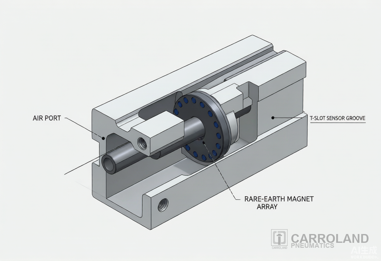
Three functional blocks define every rodless pneumatic cylinder: an internal piston driven by ported compressed air, an external carriage that carries the load, and a coupling mechanism that synchronizes the two across the cylinder wall.
flowchart LR
    A[Compressed air supply
5–8 bar regulated] --> B(Pilot 5/2 solenoid valve)
    B -- extend --> C[Internal piston
moves axially]
    C --> D{Coupling mechanism}
    D -- magnetic field --> E[Rare-earth magnet array
sealed across tube wall]
    D -- mechanical slot --> F[Steel band or cable
through slot seal]
    E --> G[External carriage
carries the load]
    F --> G
    G --> H[Workpiece / fixture]
    C -- retract --> B
    H -- position feedback --> I[T-slot magnetic sensor
ISO 15552 profile]
The diagram captures the design split that drives every selection decision: magnetic coupling variants keep the cylinder tube fully sealed and use rare-earth magnets rated at 1,200–1,500 Gauss to transfer force across the barrel wall. In contrast, mechanical variants (band and cable) carry the piston through a longitudinal slot sealed by two wipers and transfer force through a 17-4 PH stainless steel band or high-strength steel cable.
Three drive variants and their selection envelope
Once the engineer commits to a rodless pneumatic cylinder, the next decision is the drive variant. The table below distils published manufacturer data and independent engineering references into a single selection matrix.
| Drive variant | Max practical stroke | Rated load | Positioning repeatability | Max piston speed | Operating temperature | Best fit |
|---|---|---|---|---|---|---|
| Magnetic coupling | 6–8 m (limited by magnet strength) | Up to 200 kg | ±0.05–0.10 mm | Up to 3 m/s | −20 °C to +80 °C | Cleanroom, food, pharma, washdown, vacuum |
| Band (mechanical slot) | 4–5 m (limited by band fatigue) | Up to 300 kg | ±0.10–0.15 mm | Up to 2.5 m/s | −20 °C to +200 °C (high-temp seals) | General industrial, moderate contamination, moderate cycle |
| Cable (mechanical slot) | Up to 30 m (cable stretch limit) | Up to 500 kg | ±0.20–0.50 mm | Up to 2 m/s | −20 °C to +80 °C | Long-stroke transfer, high-force, harsh industrial |
The magnetic coupling variant’s closed tube makes it the only safe choice when the rodless pneumatic cylinder must operate in a class-7 cleanroom or in direct contact with a washdown zone. Band and cable designs rely on a slot seal pair that, even when properly maintained, breathes a small amount of lubricated air into the surrounding environment. Therefore, these two variants are disqualified for ISO 14644-7 zones.
ISO 15552 and ISO 21287: standards that govern rodless pneumatic cylinder selection
Two ISO standards cover most rodless pneumatic cylinder selections engineers make today:
- ISO 15552:2018 — Pneumatic fluid power — Cylinders with detachable mountings, 1 000 kPa (10 bar) series, bores from 32 mm to 320 mm. This standard was re-confirmed on 2025-02-04 at stage 90.93 (International Standard confirmed) by ISO/TC 131/SC 3. It defines basic, mounting, and accessories dimensions for interchangeability of single or double rod cylinders with or without magnetic-sensor provisions. It applies to pneumatic cylinders with detachable mountings.
- ISO 21287 — Compact pneumatic cylinders, 1 000 kPa (10 bar) series. The standard covers short-stroke cylinders typically used where envelope length is critical, in bores 20–100 mm. Most compact rodless pneumatic cylinder options on the market reference ISO 21287 bore and stroke increments even when the rodless body itself is not strictly profile-mounted.
- ISO 6432 — Mini pneumatic cylinders, 1 000 kPa (10 bar) series, bores 8–25 mm. The standard covers the smallest end of the family. It is relevant where a rodless pneumatic cylinder is being downsized from a previously specified tie-rod unit. Engineers can cross-reference our ISO 6432 vs ISO 15552 selection guide for bore-increment specifics.
When a Carroland engineer reviews an inquiry that calls out ISO 15552 dimensions but a non-standard stroke, the question to ask is whether the cylinder was actually built to ISO 15552 mounting geometry. ISO 15552:2018 governs only the mounting interfaces, not the body envelope of a rodless pneumatic cylinder. Consequently, the bore and stroke can be manufacturer-specific even when the foot, flange, or trunnion pattern is ISO 15552-compliant.
Pneumatic cylinder mounting types under ISO 15552
Mounting choice controls the side-load capacity, the allowable misalignment, and the actuator’s service life. ISO 15552:2018 defines the following mounting accessories for profile and tie-rod cylinders. The same logic applies when a rodless pneumatic cylinder is integrated into an ISO 15552-compatible machine frame.
| ISO 15552 code | Mount type | Best application | Load handling |
|---|---|---|---|
| FA / FB / FC | Foot mount (front, rear, both) | Horizontal linear motion, fixed-position push/pull | Low side load; axial thrust only |
| MA / MB / MC | Flange mount (front, rear, both) | Vertical mounting, compact envelopes, cantilever loads | Higher bending moment than foot; good for short-stroke |
| CA / CB | Clevis mount (rear / front) | Angular motion, articulated linkage, swing arms | Compensates for angular misalignment; pivot bearing recommended |
| TA / TB | Trunnion mount (head / cap) | Pivoting heavy-duty applications, large-bore cylinders | Allows rotation around a fixed axis; full thrust transfer |
| MT4 | Centre trunnion | Adjustable pivot point mid-stroke | Used where the cylinder must pivot around a load-side fulcrum |
For a rodless pneumatic cylinder the carriage itself becomes the moving mounting surface. The engineer must specify a separate external guide or integrated linear guide when the load exceeds the carriage’s intrinsic rating. Most OEM datasheets specify a maximum overhung load moment around the carriage centerline. Exceeding that moment by even 20% cuts seal life in half.
Force, cushion, and cycle-time sizing for a rodless pneumatic cylinder
Three numbers decide whether a selected rodless pneumatic cylinder will hit its rated service life on the line. They are theoretical thrust, effective thrust after load factor, and cushion stroke at the end positions.
Step 1 — Theoretical thrust
For a double-acting rodless pneumatic cylinder, thrust on the extend stroke equals:
F_thrust = A_piston × P_working × η_mechanical
where A_piston is the bore area (m²), P_working is the regulated pressure (Pa), and η_mechanical accounts for friction (typically 0.85–0.95 for a healthy rodless pneumatic cylinder). For a 50 mm bore at 6 bar (0.6 MPa) and η = 0.9, F_thrust equals roughly 1,060 N on the extend stroke. Our double-acting cylinder selection guide walks through the same calculation for standard tie-rod cylinders and shows where the assumptions differ.
Step 2 — Apply a load factor of 1.3–1.5
Industrial pneumatic sizing standards (ISO 4414 and accepted engineering practice) require the theoretical thrust to exceed the working load by a factor of 1.3 to 1.5. Picking a rodless pneumatic cylinder with a 50 mm bore to move a 60 kg payload at 6 bar (F_thrust ≈ 1,060 N) leaves a margin of (1,060 − 588) / 588 = 80% — comfortably above the 30% minimum. For validation across actuator categories, our pneumatic actuator selection guide provides side-by-side load-factor examples.
Step 3 — Cushion stroke at end positions
Most quality rodless pneumatic cylinder designs integrate adjustable air cushioning at both ends. The cushion stroke (typically 15–30 mm) absorbs the kinetic energy of the carriage and load. If the carriage mass times the square of end-of-stroke velocity exceeds the cushion’s rated energy absorption, the cushion adjustment alone will not protect the piston. In that case, the engineer must add external shock absorbers, decouple with a reduced final-approach velocity through flow control, or select a larger bore.
Application fit: where rodless pneumatic cylinders earn their place
Carroland engineers see the rodless pneumatic cylinder specified most often in four application families:
- Packaging machinery. Form-fill-seal, case packing, and labelling lines run at 60–120 cycles/min and demand precise, repeatable carriage positions. Magnetic-coupling rodless pneumatic cylinders with ±0.1 mm repeatability are a standard choice for product indexing and tray transfer. Band variants serve the heavier-duty case packer carriages.
- Automotive welding and assembly. Body-in-white welding cells need compact actuators that survive weld spatter and lubricant exposure. Band-type rodless pneumatic cylinders rated to +200 °C with stainless steel covers dominate this segment. Cable variants are reserved for long-stroke transfer between stations.
- Electronics and 3C assembly. PCBA tray handling, smartphone fixture clamping, and final-test stations require clean operation and tight envelopes. A magnetic-coupling rodless pneumatic cylinder is the default pick. Its sealed tube wall prevents lubricant migration that would contaminate the PCBA.
- Material handling and conveyor gates. Pallet positioning, container transfer, and conveyor diverters benefit from the unlimited stroke potential of cable-type rodless pneumatic cylinders. Strokes exceeding 10 m are achievable when paired with external guides.
Across these families, the same Carroland rule applies: match the drive variant to the environment first, then size the bore and stroke. In fact, that two-step decision prevents roughly 80% of the premature-failure returns we see in field failure analysis.
Maintenance and service life expectations
Manufacturer service-life test data places a properly sized rodless pneumatic cylinder at 10+ million cycles for magnetic-coupling variants and 5–8 million cycles for band and cable variants under rated conditions. Three practices keep the unit at rated life:
- Air preparation to ISO 8573-1 class 4 (or better). Solid particulate ≤ 5 µm filtration and a pressure dew point ≤ +3 °C. A 5 µm filter is the minimum to keep seal scoring off the bore. Engineers can review the upstream FRL sizing on our air preparation guide.
- Regulated pressure at the minimum required for the load. Running at 8 bar when 5 bar delivers the required thrust wastes air and raises seal wear rate. As a rule of thumb, each additional 1 bar raises energy use about 7% and accelerates seal fatigue.
- Cycle-time monitoring. A 10% slowdown on a rodless pneumatic cylinder indicates internal seal bypass, a clogged muffler, or a leaking flow-control valve. Acting on the first slowdown usually restores cycle time before seal replacement becomes necessary.
Frequently asked questions
What is the difference between a magnetic coupling and a band-type rodless pneumatic cylinder?
A magnetic coupling rodless pneumatic cylinder transfers force between the internal piston and the external carriage through a rare-earth magnet array across the sealed tube wall. A band-type variant uses a steel band that passes through a longitudinal slot in the barrel, sealed by inner and outer wipers. Magnetic coupling offers zero leakage and cleanroom compatibility, limited to roughly 200 kg load and 6–8 m stroke. Band designs handle higher loads (up to 300 kg) and higher temperatures (to +200 °C with high-temp seals) but require slot-seal maintenance and are not cleanroom-rated.
When should an engineer pick a rodless pneumatic cylinder over a standard ISO 15552 tie-rod cylinder?
Pick a rodless pneumatic cylinder when (a) installation envelope must equal stroke length, not 2× stroke. (b) The load demands a guided carriage with rated side-load capacity above 10% of thrust. (c) The environment is washdown, cleanroom, or dust-laden and the slot of a band cylinder is unacceptable. For general-purpose push-pull in a fixed orientation with no envelope constraint, an ISO 15552 tie-rod cylinder remains the lower-cost choice. Engineers can compare the bore-increment options in our ISO 6432 vs ISO 15552 vs compact selection guide.
Does ISO 15552:2018 cover rodless pneumatic cylinder dimensions?
ISO 15552:2018 (reconfirmed 2025-02-04) governs only the mounting interfaces — foot, flange, clevis, trunnion — for cylinders in the 32–320 mm bore range at 10 bar. It does not standardize the body envelope of a rodless pneumatic cylinder. Consequently, stroke length, carriage length, and overall housing remain manufacturer-specific even when the mounting pattern follows ISO 15552. For bore-mapping details, see the ISO catalogue page.
How is the cushion stroke on a rodless pneumatic cylinder adjusted?
Most rodless pneumatic cylinders expose an adjustable needle screw on each end cap that meters exhaust flow at the end of stroke. Turning the screw clockwise reduces the effective cushion orifice and lengthens the deceleration distance. Turning it counter-clockwise shortens the cushion. Set the screw so that the carriage comes to a stop without audible impact and without rebound. A correctly adjusted cushion extends seal life by absorbing kinetic energy that would otherwise reach the piston bumpers. For long-term cushion and seal inspection intervals, see our seal and maintenance guide.
What is the maximum stroke a rodless pneumatic cylinder can achieve?
The cable-type rodless pneumatic cylinder reaches the longest strokes — up to 30 m in published catalogue references — limited by cable stretch and pulley complexity. Magnetic-coupling variants max out around 6–8 m due to magnetic field decay over distance. Band-type rodless pneumatic cylinders typically top out at 4–5 m because band fatigue and slot-seal wear dominate at longer strokes.
How do magnetic position sensors integrate with a rodless pneumatic cylinder?
A rodless pneumatic cylinder built to the ISO 15552 profile carries a standard T-slot groove along the barrel that accepts reed or solid-state magnetic sensors. The sensor detects the magnet ring on the moving piston through the barrel wall without contact, providing end-of-stroke or mid-stroke position feedback to a PLC. PNP and NPN outputs are standard. Analog sensors (0–10 V or 4–20 mA output) provide continuous position for closed-loop control. Engineers can pair the sensor output with any of the valve-manifold wiring protocols in our IO-Link vs EtherCAT selection guide.
Selection checklist for a rodless pneumatic cylinder
- Confirm bore and stroke against ISO 15552:2018 / ISO 21287 envelopes.
- Match drive variant to environment: magnetic for clean/washdown, band for general industrial, cable for long stroke.
- Apply a thrust load factor of 1.3–1.5 against theoretical output.
- Verify cushion stroke absorbs end-of-stroke kinetic energy.
- Specify mounting style (foot, flange, clevis, trunnion) aligned to the load direction.
- Confirm ISO 8573-1 air quality and pressure regulation at the FRL.
A Carroland engineer can size a rodless pneumatic cylinder against your cycle-time, load, and envelope targets and ship a sample for line trial within 10 working days from Ningbo.
Carroland Pneumatics — European Technology, China Manufacturing, Since 1992.