
Pneumatic Circuit for Pick and Place Robot: Design Guide
A well-designed pneumatic circuit for pick and place robot cells moves 60 to 120 parts per minute with a 500 to 1000 ms cycle time per pick, and it does so on plant air that most facilities already own. Pneumatics still powers roughly 42% of all robotic end-effector shipments because the hardware is about 30% cheaper than comparable electric units and pays back in under 18 months. This guide walks through the circuit architecture we use in assembly cells: valve selection, end-effector logic, vacuum ejector details, and the speed-control settings that keep drop rates below 1%.
Why Pneumatic Drives in Robotics Remain the Default
Pneumatic drives in robotics dominate material handling for three measurable reasons. First, cost: a double-acting cylinder plus a 5/2 solenoid valve costs a fraction of a servo axis, and robot pneumatic grippers for robots-class tasks rarely need position feedback between two hard stops. Second, speed: direct-acting solenoid valves switch in 10 to 50 ms, so a full extend-grip-retract sequence fits inside a one-second cycle. Third, density: a pneumatic drive system in robotics delivers high force from a compact body, which matters because every gram on the end of a robot arm reduces payload available for parts. Market data confirms the trend. Asia-Pacific purchased USD 1.22 billion of pneumatic robot end effectors in 2025, a 42.94% share of the global market, and about 68% of new cobot installations still specify pneumatic grippers.
The trade-off is precision. Compressed air introduces compliance, so force control is approximate. As a result, pneumatic actuator in robotics applications suits two-position tasks — present, clamp, lift, release — while electric axes win sub-Newton assembly work such as semiconductor die placement.
Core Circuit Building Blocks
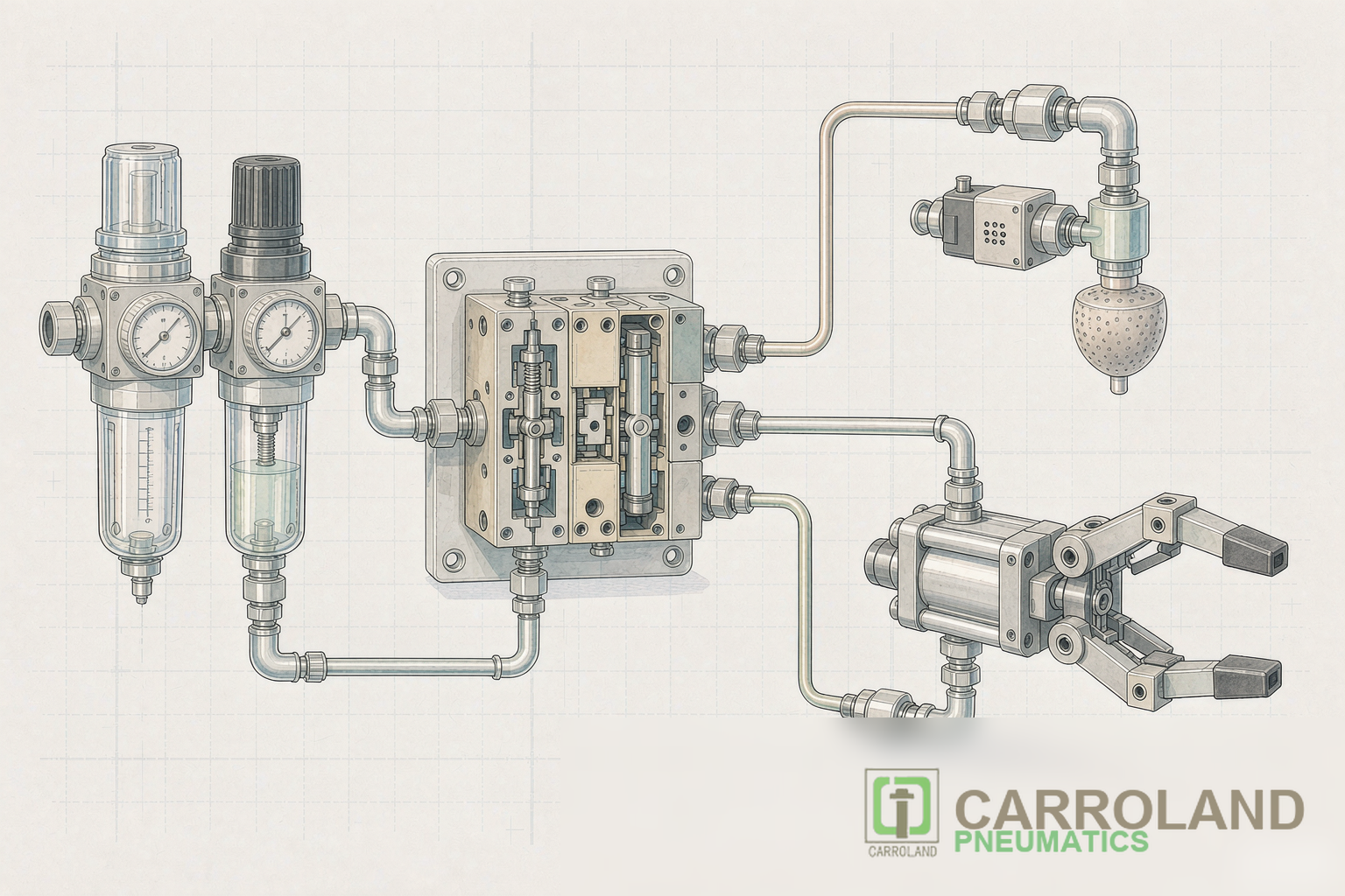
Every pick and place circuit starts downstream of the FRL unit and contains five element groups:
| Element | Typical Choice | Function |
|---|---|---|
| Air preparation | FRL, 5.5–6 bar setpoint | Clean, regulated supply; ISO 8573-1 class for the application |
| Directional control | 5/2 double-solenoid for cylinders; 3/2 NC for single-acting | Directs flow and holds last position on power loss |
| Speed control | Meter-out flow controls on both cylinder ports | 0.05–0.5 m/s stroke speed, ±2% repeatability |
| End effector | Pneumatic gripper or vacuum ejector | Part interface; gripper for solid features, vacuum for flat surfaces |
| Feedback | Reed/solid-state switches, vacuum switch | Confirms position or grip before the robot moves |
We specify double-piloted 5/2 valves for double-acting axes because the valve memorizes its state. If the PLC drops output mid-cycle, the cylinder holds position instead of retracting into the part. For axes that must fail to a safe retracted state, a single-solenoid 5/2 with spring return does that job, and for a pause position between extend and retract, a 5/3 closed-center valve blocks both cylinder ports. The notation and centre-position logic behind these choices are set out in our 5/2 vs 5/3 solenoid valve selection guide. Meter-out throttling, not meter-in, controls speed in vertical axes: restricting the exhaust side prevents the load from running away during downstrokes. Our earlier article on pneumatic circuit design for automated production lines covers valve sizing in depth.
End-Effector Logic: Types of Pneumatic Gripper and When to Use Each
Choosing among the types of pneumatic gripper decides half the circuit. A robot arm pneumatic gripper usually falls into one of three families:
- Two-jaw parallel — the standard choice for machined and molded parts with flat grip faces; about 64% of global gripper shipments.
- Three-jaw — centers round parts such as bushings and turned components; self-centering by geometry.
- Pneumatic linear gripper variants and angular bodies — compact envelopes for tight access; angular jaws swing open rather than slide, which clears the part path faster.
Pneumatic gripper working behavior is simple: supply pressure to port A opens the jaws, pressure to port B closes them, and grip force scales with supply pressure. We set gripper pressure with its own miniature regulator sized to the part. Fragile electronics run at 2 to 3 bar; structural castings run at 5 to 6 bar. We then confirm grip with a pressure switch set about 15% below the regulator setpoint. If the switch sees pressure loss mid-cycle, the robot stops instead of carrying a loose part. For deeper selection criteria, see our air gripper types and robot integration guide.
Vacuum Ejector Sub-Circuits: Three Details That Cause Failures
Vacuum handles flat, non-porous, or delicate parts that jaws would mark. A venturi ejector converts supply air into vacuum with no moving parts, but the sub-circuit needs care:
Detail 1 — valve type. A 2/2 valve with an internal air pilot needs minimum supply pressure at port 1 to shift. Connected on the vacuum side, that pressure never arrives, so the valve stays shut and the circuit deadlocks. The fix is a direct-operated solenoid valve, which shifts under vacuum without a pilot.
Detail 2 — energy. An ejector consumes compressed air continuously while energized, even during travel between pick and place. A 3/2 valve between supply and ejector cuts consumption during non-pick phases; over a 500 ms cycle, that approach measurably lowers compressor load.
Detail 3 — release. Parts stick to cups at placement. Two solutions work: a brief positive-pressure blow-off pulse through a second valve, or ejector shutoff plus blow-off combined. We always fit a speed control in the release line because unrestricted blow-off can bounce a light part off its target position.
Speed Control and Cycle Time Budget
A cell rated at 90 picks per minute has roughly 660 ms for the complete sequence. A practical budget for a two-axis pick and place head looks like this:
| Phase | Time | Control Lever |
|---|---|---|
| Extend to pick | 150–250 ms | Meter-out setting, valve Cv |
| Grip confirmation | 30–80 ms | Vacuum switch threshold, pressure switch |
| Transfer | 200–300 ms | Robot motion, not the pneumatic circuit |
| Release | 50–100 ms | Blow-off pulse width |
Valve response sits inside these numbers. Direct-acting solenoids shift in 10 to 50 ms; pilot-operated valves need 20 to 100 ms and a minimum pilot pressure. For cycle rates above 60 per minute we stay with direct-acting bodies, and we verify speed repeatability over 50 consecutive cycles during commissioning — an uncalibrated throttle shows 5 to 15% stroke-to-stroke variation, which shows up later as drift in drop rate. Stroke speed and dwell ultimately trace back to cylinder force and bore sizing, which we fix before trimming flow controls.
Safety and Standards Notes
Collaborative cells must comply with ISO/TS 15066 power and force limiting; compliant-bodied pneumatic grippers with rounded fingers and low closing forces were widely adopted for this reason in 2025. Additionally, safety-rated exhaust and a fail-safe gripper state (normally closed under air loss) belong in any cell where a dropped part could injure an operator.
Conclusion
A reliable pick and place circuit is five decisions made in order. They are supply quality, valve logic matched to fail-state requirements, gripper type matched to part geometry, vacuum sub-circuit with proper release, and speed settings verified against a cycle-time budget. Each decision has a measurable acceptance test — pressure, response time, repeatability over 50 cycles, drop rate below 1%. Specify them in the purchase order, and the circuit behaves on day one.
FAQ
How does a pneumatic gripper working principle differ from an electric gripper?
A pneumatic gripper converts supply pressure into jaw force through a piston, so force follows pressure and travel follows the cylinder stroke. An electric gripper uses a motor-driven spindle and can stop at any commanded position with force feedback. For two-position pick and place tasks, the pneumatic option is faster to integrate and roughly 30% lower in cost.
Why does my vacuum cup fail to release parts cleanly?
The part seals against the cup at placement because vacuum persists. Cut the ejector supply and add a short positive-pressure pulse through the pad, with a flow control limiting the pulse so the part lands where placed instead of bouncing off the target.
What air pressure should a pick and place circuit run at?
Most industrial cells run 5.5 to 6 bar at the FRL. Cylinders and grippers size their force from that pressure, and valve datasheets assume it, so dropping below 4.5 bar risks pilot-operated valves failing to shift and grip force falling below the pressure-switch threshold.
Can one robot use both gripper and vacuum on the same circuit?
Yes. Tool changers with air pass-through are common — pneumatic tool changers took about 11% of the 2025 end-effector market. Give each function its own valve and regulator so gripper pressure changes do not disturb ejector supply.