
Solenoid Coil Guide for Pneumatic Valves: Selection & Replacement
A solenoid coil converts electrical energy into the linear magnetic force that shifts a pneumatic valve spool. Engineers often treat the coil as an afterthought, yet a mismatched coil causes more field failures than any other valve sub-assembly. This guide covers coil voltage, power, duty cycle, and failure modes so you can specify the right part for continuous-duty automation lines.
What a Solenoid Coil Does in a Pneumatic Valve
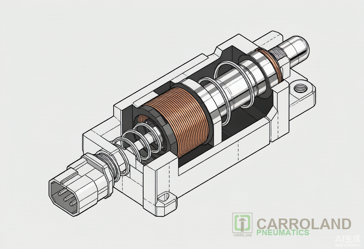
For example, when the controller energises the coil, current flows through the copper winding and creates a magnetic field. The field pulls the armature (plunger) against the spring, opening or closing the valve ports. When the controller de-energises the coil, the spring returns the plunger to its rest position. In a solenoid operated valve, this cycle repeats millions of times over the service life of the machine.
The coil does not move air directly; instead, it provides the force that overcomes spring pressure and internal friction. For this reason, coil selection depends on four linked parameters: voltage, power, duty cycle, and ambient temperature.
AC vs DC Solenoid Coils: Trade-offs in Real Production Lines
Automation cabinets today run mostly on 24 VDC, but 110 VAC and 220 VAC coils remain common in older plants. Each power type creates a different thermal and electrical signature.
| Parameter | AC Coil | DC Coil |
|---|---|---|
| Initial pull-in force | High inrush current, fast shift | Lower, consistent force |
| Continuous power | Typically 6–12 W holding | Typically 2–6 W holding |
| Heat generation | Higher; burnout risk if plunger stalls | Lower; better for continuous duty |
| Acoustic noise | May hum at 50/60 Hz | Quiet operation |
| Best application | Rapid cycling, intermittent duty | Always-on control systems |
DC coils dominate new machine builds because they run cooler and draw steady current. However, AC coils still make sense where a large inrush force must overcome a sticky spool or where the plant electrical standard is AC-only. For a 24 VDC panel, a pneumatic valve solenoid guide will list the exact wattage and connector form so the coil matches the PLC output card.
Voltage, Power, and Duty Cycle Selection
Voltage mismatch is the leading cause of premature coil failure. For example, a 24 VDC coil energised at 20 V may not generate enough magnetic force to shift the spool fully. As a result, the valve chatters, heat builds, and the coil burns out. In contrast, a 24 VDC coil energised at 30 V draws excess current and overheats. Always match the rated voltage within ±10 %.
Power consumption falls into three bands used by most manufacturers:
- Standard: ~10 W — high force, acceptable for short duty cycles.
- Reduced: ≤4 W — common for pilot-spool valves in general automation.
- Low: ≤2 W — suitable for battery-backed or energy-conscious systems.
Duty cycle defines the percentage of time the coil may remain energised. Therefore, a 100 % ED (electrical duty) coil can stay on continuously, while a 50 % ED coil must cool for half the cycle. If your valve stays open for ten minutes and then closes for ten minutes, specify 100 % ED even though the mechanical duty is only 50 %.
Coil Failure Modes and Diagnostics
Field teams can diagnose most coil problems with a multimeter and a thermal camera. The three most common failure modes are:
- Burnout from over-voltage or stalled plunger. The coil resistance rises until the winding opens. Symptom: infinite resistance across the coil terminals.
- Shorted turns from moisture or chemical attack. The coil draws high current but produces weak magnetic force. Symptom: low resistance and localised overheating.
- Connector corrosion. Voltage reaches the coil terminals but current is intermittent. Symptom: valve shifts only when the cable is wiggled.
A good maintenance practice is to record coil resistance and surface temperature during commissioning. A coil that runs 20 °C hotter than identical units on the same manifold is likely failing. Replacing the coil instead of the whole valve cuts downtime cost by 60–80 % in most plants. Coil reliability also depends on the upstream air quality; water, oil aerosol, and particulate contamination accelerate insulation failure long before mechanical wear sets in. The accepted air-purity reference for pneumatic systems is ISO 8573-1, summarised in our air preparation unit ISO 8573-1 guide.
Seal Materials and Ambient Conditions
The coil must survive the ambient conditions around the valve, not just the air inside it. As a result, standard coils use Class B or Class F insulation with temperature limits of 130 °C or 155 °C respectively. In practice, keep the coil surface below 80 °C to preserve cable and connector life.
| Seal / Insulation | Typical Limit | Recommended Use |
|---|---|---|
| NBR coil seal | −10 °C to +80 °C | Clean compressed air, indoor cabinets |
| FKM (Viton) coil seal | −20 °C to +150 °C | High-temperature or oily atmospheres |
| Class B insulation | 130 °C winding limit | General industrial duty |
| Class F insulation | 155 °C winding limit | Continuous-duty or hot environments |
Ingress protection matters on the plant floor. Most automation valves carry IP65 or IP67 ratings. IP65 resists dust and low-pressure water jets; IP67 tolerates temporary immersion. If operators wash down the area, specify IP67 and a cable gland rather than a loose DIN connector.
Industry Applications
Solenoid coils appear in almost every pneumatic circuit, but the specification changes with the application. For example, in packaging machines, rapid cycling demands a coil with fast response and good heat rejection. In semiconductor cleanrooms, low-outgassing insulation and low particle generation take priority. Automotive welding lines subject coils to weld spatter and electromagnetic noise, so shielded cables and high-temperature seals pay back quickly.
For 3C assembly lines, the governing concern is repeatable timing. A valve that shifts in 16 ms instead of 40 ms can cycle a clamp 50 % more often on the same takt time. When you size the coil for these cells, match the PLC output current and verify the voltage drop along the cable run. The valve and cylinder together define the cycle budget for these cells; the pneumatic system for 3C automation guide covers the full manifold-to-clamp architecture that 3C automation builders use on iPhone, tablet, and smartwatch lines.
FAQ
Can I replace a 24 VDC coil with a 220 VAC coil on the same valve body?
Yes, if the valve body and spool are identical and the coil form factor matches. The coil is a separate sub-assembly. Always check the manufacturer datasheet: the power rating, duty cycle, and connector orientation must suit your supply.
Why does my solenoid coil get hot even when the valve is not actuating?
The coil consumes holding current for as long as it is energised. Therefore, in a continuous-duty application, a DC coil with low wattage will run warm but within specification. However, if the temperature exceeds the insulation class limit, verify the supply voltage, duty cycle rating, and whether the plunger is fully seated.
How do I measure whether a coil has failed?
Disconnect power and measure resistance across the coil terminals. Compare the reading to the datasheet. An open circuit means burnout; a much lower reading than specified indicates shorted turns. A thermal camera can reveal hot spots before the coil fails completely.
What is the difference between a solenoid coil and a solenoid sensor?
The coil is the actuator that moves the valve. A solenoid sensor, often a valve-position indicator or a magnetic switch, reports whether the valve has shifted. The two components sit on or near the valve but perform different functions.
Should I choose 100 % duty cycle for every application?
No. A 100 % ED coil costs more and runs warmer than necessary for intermittent duty. If the valve cycles once per minute and stays energised for five seconds, a 50 % ED coil is sufficient. Match the duty cycle to the real operating pattern.
Conclusion
Therefore, specifying a solenoid coil is a risk-management decision, not a parts-list afterthought. Match the voltage exactly, size the power for the duty cycle, and choose insulation and sealing for the ambient environment. For high-cycle automation, prefer DC coils with low holding power. When a coil fails, diagnose resistance and temperature first; replacing the coil usually restores the valve faster and at lower cost than replacing the entire assembly.
For a deeper look at complete valve selection, see our pneumatic valve and solenoid guide. You can also review international compressed-air quality guidance at the ISO 8573-1 page.