
Parts of a Pneumatic System: A Component Checklist for Engineers
The parts of a pneumatic system span from the air source to the final actuator, with preparation and control stages between. A clear parts list prevents missing components during design and commissioning. In this guide, we enumerate the parts of a pneumatic system and explain the job of each.
The Complete Parts List
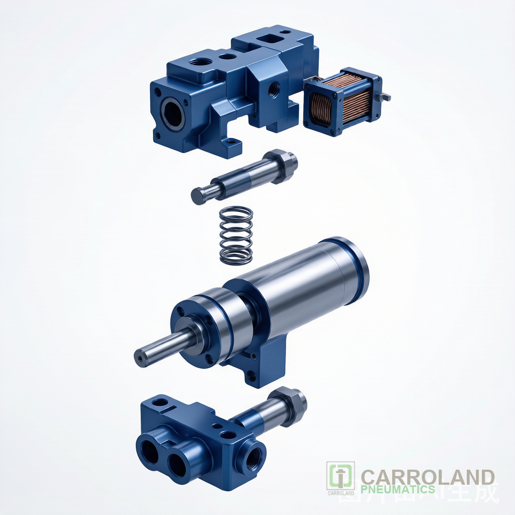
The parts of a pneumatic system fall into five blocks. First is the source: compressor and receiver. Second is preparation: filter, regulator, lubricator. Third is distribution: main line, branches, and push-in fittings. Fourth is control: solenoid valves, manifolds, and sensors. Fifth is actuation: cylinders, grippers, and rotary actuators. In short, every working line contains all five.
Parts of a Pneumatic System: Reference Table
| Stage | Parts | Function |
|---|---|---|
| Source | Compressor, receiver, dryer | Make and store clean air |
| Preparation | Filter, regulator, lubricator (FRL) | Clean, set pressure, lubricate |
| Distribution | Main line, fittings, tubing | Carry air to devices |
| Control | Solenoid valves, manifolds, sensors | Route and switch flow |
| Actuation | Cylinders, grippers, rotary actuators | Convert air to motion |
How the Parts Connect
Air leaves the compressor, passes the FRL, travels the line, reaches the valve, and drives the cylinder. For example, a clamp cycle energizes a valve that extends a cylinder to hold a part. Consequently, a fault in any part stops the whole action. Therefore, commissioning should test each stage in order, from source to actuator.
Specifying Each Part
| Part | Key spec |
|---|---|
| Compressor | Free air delivery, pressure |
| FRL | Flow, filtration grade, regulator range |
| Fittings | Tube OD, thread, material |
| Solenoid valve | Way/position, Kv, voltage |
| Cylinder | Bore, stroke, ISO standard |
Standards Behind the Parts
Cylinders meet ISO 15552 or ISO 6432. Valves meet ISO 15217-1. Air quality meets ISO 8573-1. In addition, CE marking applies across the EU. As a result, specifying standard parts eases global support. For cylinder standards in detail, see our ISO 6432 vs 15552 guide.
Detailed Part Descriptions
The compressor makes air; the receiver buffers it against demand spikes. The filter removes particles and condensate; the regulator holds set pressure; the lubricator adds a thin oil film to seals. Tubing and push-in fittings carry air with low loss. Solenoid valves switch it; cylinders and grippers turn it into work. In short, each part has one job, and the line fails if any is missing.
Sensors and Feedback Parts
Position sensors, pressure switches, and flow meters are the nervous system of the system. For example, a reed switch confirms a cylinder reached end stroke. Similarly, a pressure sensor detects a dropped line before a fault. Consequently, adding these parts turns a basic loop into a controllable one that a PLC can trust.
Commissioning Checklist
| Stage | Commissioning check |
|---|---|
| Source | Pressure and dew point at spec |
| Preparation | FRL drains, regulator stable |
| Distribution | No leaks, pressure at ends |
| Control | Each valve shifts on command |
| Actuation | Cylinder reaches both ends |
Frequently Asked Questions
Which parts of a pneumatic system need daily checks?
The FRL filter bowl and pressure gauge. However, automated lines often monitor these remotely.
Can I mix brands across the parts?
Yes, when interfaces and ISO standards match. Meanwhile, keep spares for the wear parts: seals and filter elements.
What part most affects cycle time?
The valve and its response time, then the cylinder bore and line pressure. Our sizing guide helps you balance them.
Typical Bill of Materials for a Clamp Station
A single clamp station needs these parts: one compressor tap or shared line, one FRL, one 5/2 solenoid valve, one double-acting cylinder, two push-in fittings, one silencer, and one position sensor. In short, the five-stage list collapses to a real shopping list. Moreover, add a quick-exhaust for fast drop on e-stop.
Common Parts Mistakes
Builders often forget the silencer, so the exhaust noise fails the cell. Similarly, they omit the sensor and wonder why the PLC guesses position. As a result, a complete parts list prevents both field rework and safety gaps.
What is the most common missing part?
The FRL or the position sensor. Both seem optional until the first failure, then become mandatory. Therefore, include them in the base spec.
Do I need a regulator if pressure is stable?
Yes. Local regulation protects the station from plant swings and lets you tune force per task. Consequently, a regulator is cheaper than a scrapped part.
Can one parts list serve many stations?
Yes, with a standard cell template. Therefore, repeating the same parts list cuts training and spares cost across the line.
How many fittings should I budget?
Count each tube end plus spares; a typical clamp station uses four to six. As a result, a small fitting kit avoids a mid-build stop.
What about tubing size?
Match tube OD to the valve port, usually 6 or 8 mm for compact stations. Therefore, oversized tube adds cost, undersized starves flow.
What spares should sit at the cell?
One seal kit, two filter elements, one spare valve, and a few fittings cover most stops. Consequently, a small drawer beats a line-down wait for a shipment.
How do I label parts for fast service?
Tag each valve and cylinder with its code and a QR to the manual. Therefore, a new technician finds the right part in seconds, not in a drawer of look-alikes.
See pneumatic fixture design guide and FRL preparation guide. For component sourcing, review our supplier evaluation framework.
Standard: ISO 8573-1 air quality.