
Selector Valve and SOV Valve Types: A Circuit Selection Guide
A selector valve answers a question every dual-source pneumatic circuit asks: which supply line feeds the actuator right now? Two component families handle the job. A passive shuttle element shifts on pressure alone, while a solenoid-operated valve (SOV) switches on a PLC command. Both sit between supply and actuator, and both must stop one source from pushing air back into the other. This guide works through the logic, the port-configuration codes, ISO 6358 flow sizing and coil data, so an engineer can release a bill of materials with fewer iteration loops.
What a Selector Valve Does in a Pneumatic Circuit
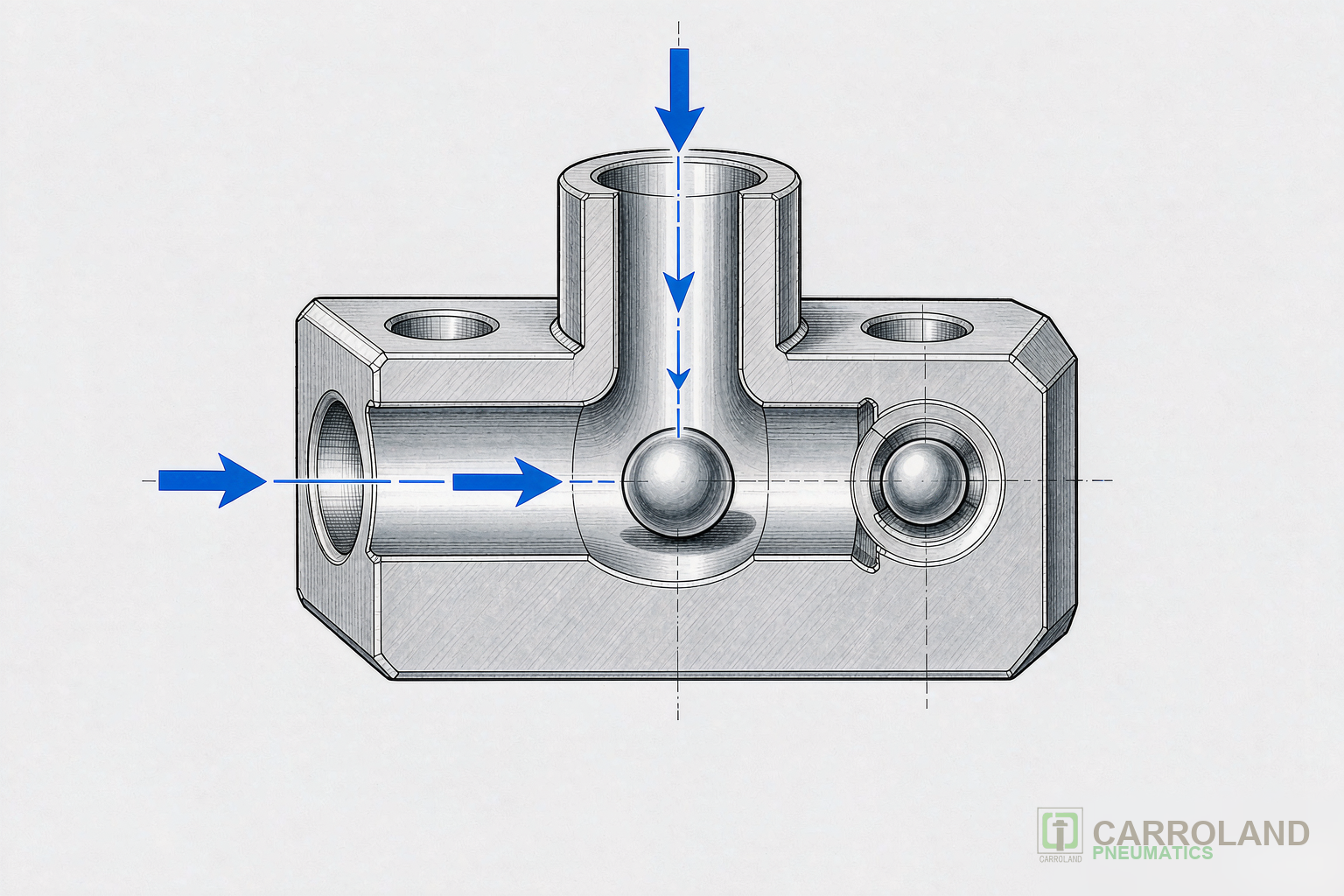
A shuttle-type selector valve carries three ports: two inlets and one outlet. A free ball or sliding spool moves inside the bore between them. Air entering inlet A pushes the element against inlet B, seals it, and opens the path to the outlet. Reverse the pressures and the element travels the other way. The output therefore follows pneumatic OR logic: Y = A + B.
The element needs a small pressure difference to shift. Published cracking differentials for compact shuttle valves fall between 0.02 and 0.05 MPa (0.2 to 0.5 bar), and standard bodies handle 0.05 to 1.0 MPa. When both inputs are pressurized, the higher pressure wins and seals the lower line, so the weaker source cannot vent to atmosphere through the idle inlet.
That sealing behavior is the reason a plain T-connector cannot do this job. With a T-piece, one pressurized inlet and one idle inlet would simply leak the whole supply through the open branch, and the actuator would never move. A selector valve closes that idle branch on every cycle.
Selector Valve, Check Valve and Directional Control Valve Compared
A check valve has two ports and blocks reverse flow in one line. A selector valve has three ports and arbitrates between two lines. A directional control valve, by contrast, routes supply and exhaust between several ports in defined switched positions. Table 1 lines the three up.
| Property | Check valve | Selector valve (shuttle) | Directional control valve |
|---|---|---|---|
| Ports | 2 (1 in, 1 out) | 3 (2 in, 1 out) | 2/2 to 5/3 by function code |
| Logic role | Non-return only | OR gate, picks the higher pressure | Routing, memory and exhaust control |
| Actuation | Media pressure | Media pressure, no power needed | Solenoid, air pilot, mechanical or manual |
| Typical cracking band | 0.01 to 0.03 MPa | 0.02 to 0.05 MPa | Piloted types need about 1.5 bar minimum |
| Best fit | Anti-backflow on one branch | Two-source sharing, manual-auto changeover | Cylinder and rotary actuator control |
SOV Valve Types: Direct Acting, Pilot Operated and Manifold Mounted
The common SOV valve types separate by how the armature does its work. In a direct-acting valve the armature lifts the orifice seal itself, so the valve starts from 0 bar and needs no minimum pilot pressure. The cost is coil power: direct-acting bodies typically draw 15 to 30 W because the coil must overcome full line pressure. In a pilot-operated valve the solenoid only opens a small control orifice, and line pressure does the main switching. The coil therefore drops to 2 to 8 W, while the same body size passes far more flow. The trade-off is a minimum pilot pressure, usually around 1.5 bar, and external piloting whenever the line runs vacuum or very low pressure.
Construction matters as much as the coil. Body materials range from brass with nickel plating for standard shop air to 316 stainless steel for washdown and corrosive media, and seal compounds (NBR, FKM, EPDM) decide chemical compatibility. For a deeper treatment of the underlying component, see our pneumatic valve overview.
Port functions: 2/2, 3/2, 5/2 and 4/3
The function code reads as ports/positions. A 2/2 valve simply opens or closes one path. A 3/2 valve adds a vented rest position, which suits single-acting cylinders and any clamp that must release when power fails. A 5/2 valve feeds a double-acting cylinder in both directions. A 4/3 DC valve adds a third, neutral center that can be closed, exhausted or pressurized, which gives designers controlled mid-stroke stopping. For electronics assembly fixtures, the normally closed 3/2 and the spring-return 5/2 cover most clamping duty.
5/2 Way Directional Control Valve vs 3/2 Way Directional Control Valve
For a double-acting clamping cylinder, a 5/2 way directional control valve is the default choice: port 1 receives supply, ports 2 and 4 feed the two cylinder chambers, and ports 3 and 5 exhaust. A single-solenoid spring-return version gives a defined safe position whenever power drops, which matters on fixtures near an operator. A 3/2 way directional control valve drives single-acting cylinders, air springs and pilot signals; its vented rest position keeps the actuator unloaded without trapping pressure.
Function Symbols (ISO 1219-1 style)
3/2 NC
single-acting, vented rest
5/2
double-acting, spring return
4/3 center options
closed, exhausted or pressurized
Arrows show flow paths in the active position; the crossed or blocked symbols show the rest position.
Schematic representation, not to scale.
Sizing with ISO 6358 Conductance and the ISO 5599-1 Interface
Port thread size alone misleads. Two valves with the same G1/4 ports can differ by a factor of three in real flow. ISO 6358 therefore characterizes each valve by two measured values: sonic conductance C in dm³/(s·bar) and the critical pressure ratio b. For real valves b sits between 0.2 and 0.5, while an ideal nozzle gives 0.528. Once the downstream-to-upstream absolute pressure ratio P2/P1 drops below b, the flow chokes and Q = C · P1 · √(T0/T); lowering downstream pressure further changes nothing. In the subsonic region above b, the standard’s correction formula applies instead.
Conversion to legacy coefficients follows fixed factors: Cv ≈ 0.2955 · C and Kv ≈ 0.2556 · C. Suppliers publish them on different bases, so always check which coefficient and which basis a data sheet quotes before comparing two valves.
The mounting side has its own standard. ISO 5599-1:2001, edition 3, was reconfirmed in May 2024 and fixes the five-port interface for valves up to 1.6 MPa (16 bar). Port 1 is pressure, ports 2 and 4 are working ports, and ports 3 and 5 are exhausts. Size 1 uses a nominal 8 mm bore and reaches roughly 1,080 Nl/min; size 2 moves to 13 mm and about 2,200 Nl/min; size 3 extends the series for 1/2-inch ports. Because the ISO 5599-1 interface also standardizes the sub-base, individual valves bolt into serviceable manifold islands with one shared supply and a common exhaust. For electrical integration of such islands, our IO-Link vs EtherCAT valve manifold guide covers the fieldbus options.
| ISO 5599-1 size | Nominal bore | Typical nominal flow | Typical Cv band | Common ports |
|---|---|---|---|---|
| Size 1 | 8 mm | about 1,080 Nl/min | 0.8 to 1.0 | G1/4 |
| Size 2 | 13 mm | about 2,200 Nl/min | 1.9 to 2.0 | G3/8 |
| Size 3 | larger spool series | about 4,000 Nl/min class | 3.8 to 4.4 | G1/2 |
Coil Selection: DC Solenoid vs AC Solenoid Coil
A DC solenoid draws a constant current set by winding resistance, so inrush and holding current are the same and a stuck armature stays a low-risk event. An AC solenoid coil is current-limited by inductive reactance instead. With the armature open, the air gap is large and inductance is low. Inrush can then reach 5 to 10 times the seated holding value for roughly 20 to 50 ms. If debris keeps the plunger from seating, the coil stays at inrush and overheats within seconds; that is the classic AC burnout path. An AC winding also carries a copper shading ring on the pole face to suppress the 100 or 120 Hz hum, and the two coil types are not interchangeable.
Thermal limits come next. Insulation class under IEC 60085 sets the winding hot-spot ceiling: Class A 105 °C, Class B 130 °C, Class F 155 °C and Class H 180 °C. Operating a winding about 8 to 10 K above its class roughly halves insulation life, so Class F or H is the sensible baseline for industrial coils. Duty cycle (ED) matters in parallel. A coil rated for intermittent service overheats if the process holds it energized for hours, so specify 100% ED wherever clamps stay closed through a shift.
Protection and wiring finish the specification. IP65 covers dust-tight construction with low-pressure jet resistance; washdown lines need IP67 or IP69K with fully potted coils. The DIN EN 175301-803 Form A connector remains the default interface and keeps spares interchangeable. For new machine builds, 24 V DC dominates because it connects straight to PLC output cards without interposing relays and avoids inrush sizing. Our solenoid coil guide covers replacement and voltage selection in detail.
Applying Selector Valves and SOVs on Assembly Lines
On 3C and electronics assembly stations, the selector valve earns its place in three circuits. First, manual-auto changeover: a shuttle valve merges the hand-lever pilot line with the PLC pilot line, so maintenance staff can jog a clamp while the machine stays wired for automatic mode. Second, redundant supply: the standby tank sits a few tenths of a bar below the main header, and the shuttle hands over automatically when the compressor unloads. Third, two-hand control blocks, where the selector combines actuation signals without adding electrical logic.
Sizing follows the signal, not the port. For pilot signals on fast fixtures, keep the valve conductance high enough that signal propagation stays below 20 ms. In practice that means Cv of roughly 0.5 or more on compact shuttle valves for high-speed packaging and assembly lines. On the power side, match the SOV conductance to the cylinder. A 5/2 size 1 valve covers most 32 to 50 mm clamping bores at 4 to 6 bar, while heavier forming fixtures step up to size 2. Designers who combine both stages on one manifold cut piping length and commissioning time; the safety rules for the surrounding system are set by ISO 4414.
Selection Checklist
- Use a shuttle-type selector valve wherever two sources share one load and must never cross-vent.
- Match SOV construction to pressure: direct acting from 0 bar, pilot operated above about 1.5 bar with lower coil power.
- Size by ISO 6358 conductance and the required stroke time, never by port thread alone.
- Prefer 24 V DC coils with Class F or H insulation and 100% ED for clamping that stays closed all shift.
- Standardize on ISO 5599-1 sub-bases so manifolds and spares stay serviceable across machine generations.
Frequently Asked Questions
Can a selector valve replace a check valve?
No. A check valve blocks reverse flow in a single line with two ports. A selector valve has three ports and actively picks the higher of two inputs while sealing the lower one. The two components solve different problems, although both rely on pressure-driven elements.
Can a shuttle valve implement AND logic?
No. A shuttle valve outputs pressure when at least one input is pressurized, which is OR logic. AND logic needs a two-pressure valve (a dual-pressure element) that only passes flow when both inputs are live, or an electrical interlock in the controller.
Which valve function suits a double-acting clamping cylinder?
A 5/2 single-solenoid, spring-return valve is the standard answer. The spring position vents both chambers in a defined way, so the clamp either opens or closes safely on power loss depending on how the designer assigns ports 2 and 4.
Why does an AC coil fail while the valve still works?
Contamination or a swollen seal keeps the armature from seating. The coil then remains at inrush current, 5 to 10 times its holding value, and the winding exceeds its insulation class within seconds. A DC coil on the same valve would survive the same mechanical jam because its current does not depend on armature position.