
Pneumatic Cylinder Reed Switch Working Principle Explained
Understanding pneumatic cylinder reed switch working is mostly a matter of following a magnetic field through three materials: the piston magnet, the aluminium barrel wall, and the thin ferromagnetic blades inside a sealed glass capsule. Nothing in the chain is electronic until the contact closes, which is exactly why the device survives in workshops where dust, oil mist and voltage spikes ruin more sophisticated sensors. Carroland Pneumatics supplies ISO 15552 and ISO 21287 cylinders with magnetic pistons and matching reed sensors to Indian OEMs, and this page explains the mechanism, the timing and the failure modes in engineering detail. European Technology, China Manufacturing, Since 1992.
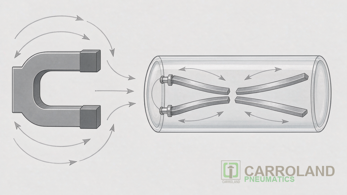
The Field Path from Piston to Blade
A permanent magnet ring sits inside the piston, concentric with the bore. The barrel wall is aluminium, which is non-ferromagnetic and therefore almost transparent to the field; a stainless-steel body would shield it, which is why sensing on stainless round bodies needs a different sensor geometry. The field emerges into the barrel groove, where the reed capsule rests, and its strength falls with the square of the distance. That inverse-square behaviour explains the practical rules: the sensor must sit within about 4 mm of the barrel surface, the magnet ring must be at least 3 mm thick to produce a usable field at that distance, and a sensor designed for a 15552 groove will not reliably detect a thick-walled barrel from the same mounting position.
How the Contact Closes
Two blades of a nickel-iron alloy are sealed into a glass tube filled with inert gas, with a small overlap gap between their tips. When the axial component of the magnetic field reaches the blade tips, the blades become magnetised with opposite polarity and attract each other until the gap closes. Because the blades are the moving parts, the contact is a mechanical device with mass, and that mass sets both the switching speed and the vulnerability to shock. The sealed capsule protects the contacts from moisture and contamination but not from mechanical shock transmitted through the barrel, which is why reed sensors are not the first choice on pneumatic hammers or high-vibration compactors.
Pull-In, Drop-Out and Hysteresis
The contact does not close and open at the same field strength. Pull-in occurs at a higher field than drop-out, and the difference, expressed as a travel distance, is the sensor hysteresis, typically a few millimetres on a standard groove sensor. Hysteresis is useful: it stops the output from chattering while the piston passes slowly through the threshold. It also means the reported end position is offset from the mechanical end position by that distance plus the mounting tolerance. Controllers that need a precise position reference should account for the offset in the program rather than assuming the signal marks the exact end of stroke.
Timing: Bounce, Response and Switching Frequency
Closing takes under 1 ms, and during that closure the contact bounces for roughly 0.1 to 0.5 ms before settling. The bounce is invisible to a relay driving the same valve coil, and very visible to a high-speed counter, so PLC input filtering is part of correct design. Maximum switching frequency is bounded by the time the blades need to settle and release; a small sensor can follow a few hundred hertz, which comfortably covers end-of-stroke confirmation and excludes pulse-counting duty. Where a machine logs strokes at high rate, a Hall effect sensor with an electronic output removes the bounce and the frequency limit together.
From the Sensor to the Solenoid Valve Working Cycle
The sensor answers a question that the solenoid valve working cycle asks. A 5/2 valve is commanded to extend, the piston travels, the extend sensor closes, and the controller then commands the retract or the next station. If the signal does not arrive within the expected window, the controller has four explanations to choose from, and a reed switch narrows them quickly: no air pressure, a seized cylinder, a stuck valve spool, or a failed sensor. Because the sensor output is a simple dry contact, it can be wired in series with a relay coil without any supply, which is why retrofit work on older Indian machines so often ends with a reed sensor rather than a networked sensor block.
Groove Options on a Round Cylinder and a Round Body Air Cylinder
A round cylinder has no T-slot, so sensing is handled by a bracket that straps the sensor against the barrel, or by a band clamp positioned with a feeler gauge. Detection works, but the sensor cannot slide freely for trimming, and the switching point is set by bracket position rather than by a groove. A round body air cylinder with a groove, offered on some compact bodies, keeps the mounting convenience of a profile cylinder in a smaller envelope. When a project moves from profile to round bodies for space reasons, sensing should be re-checked at the design stage rather than at commissioning.
Common Failure Modes and How to Avoid Them
Five failures account for most field returns. Contact welding from switching a load above the rated power, which is why the 10 W ceiling on a 2-wire sensor is a real limit rather than a suggestion. Blade fatigue from constant vibration where the bracket or the sensor screw is loose. Water ingress through a damaged cable entry, cured by a drip loop and by keeping the air preparation on schedule. Welding spatter melting a plastic housing, cured by a protective cover or a position change. And crosstalk from an adjacent cylinder, cured by a Hall sensor or by orienting the sensors away from the neighbouring magnet.
Rotary Sensing on a Pneumatic Rack and Pinion Actuator
The same magnetic principle scales to rotary motion. A quarter-turn pneumatic rack and pinion actuator uses a sensor box with two reed contacts set against the travel stops, giving open and closed confirmation without a shaft encoder. Because the stops are mechanical, the switch points can be trimmed with a cam, and because the actuator holds torque rather than position, the sensor is verifying the stop rather than a controlled angle. For a valve that must report three positions, the box is replaced by a multi-position unit, and the mounting interface remains the standard one.
Sourcing, Suppliers and Documentation
When buying from pneumatic suppliers, a pneumatic parts supplier or pneumatic valve manufacturers, treat the sensor as part of the cylinder specification. The three questions worth asking are the groove family the sensor fits, its switching life and IP rating, and the magnet grade used in the piston, since a weaker magnet shortens the usable sensing distance and makes the switch point sensitive to barrel thickness. Indian electronics and semiconductor manufacturing is the fastest-growing pneumatic end use in the country at roughly 14 to 18 percent annually, and those lines are the ones that depend most on a clean, repeatable end-position signal.
Frequently Asked Questions
Why does the reed switch only work near one end of the stroke?
Either the piston magnet is missing, or the sensor is mounted at a point where the field does not reach the blades. Confirm that the cylinder has a magnetic piston, then slide the sensor along the groove while watching the LED to find the working band.
Can a reed switch drive a solenoid valve coil directly?
Only within the contact power rating, typically 10 W in a 2-wire circuit. Valve coils with inrush current above that figure require a relay or a PLC output stage between the sensor and the coil, otherwise the contact will weld closed over time.
What is the difference between a reed sensor and a proximity sensor on a cylinder?
A reed sensor detects the piston magnet and needs a magnetic piston to work. An inductive proximity sensor detects ferrous metal and can be aimed at a target on the machine, which is useful where the cylinder cannot be specified with a magnet.
Continue with the pillar guide to pneumatic cylinder types for Indian manufacturers, and the companion pages on reed switch selection and mounting and magnetic piston cylinders. Standards for the cylinder envelope are listed in the ISO standards catalogue, and Indian compliance questions start at the Bureau of Indian Standards.