
Pneumatic Cylinder Magnetic Reed Switch: Working Principle
The pneumatic cylinder magnetic reed switch is the least expensive way to give a machine the ability to confirm where its actuator actually is. Two ferromagnetic blades sealed in a glass capsule close when the piston magnet passes, and that simple contact still outnumbers every other position-sensing technology on Indian factory floors. Carroland Pneumatics supplies ISO 15552 profile cylinders, ISO 21287 compact cylinders and matching reed sensors to Indian OEMs and system integrators. This page explains how the device works, how it is mounted and how it fails. European Technology, China Manufacturing, Since 1992.
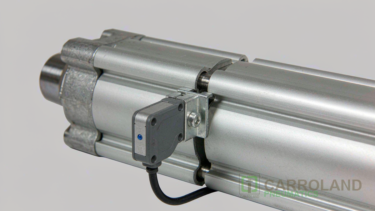
The Magnetic Path from Piston to Reed Blade
Inside the capsule, two thin blades of ferromagnetic material overlap with a small air gap. In the presence of a magnetic field aligned with the capsule axis, the blades become magnetised, attract each other and close the circuit. Remove the field and the blades spring apart. The capsule is filled with an inert gas and the contacts are usually plated. That construction allows a contact rated for a few tens of milliamps to survive millions of operations in a dusty workshop.
Field strength at the blades falls quickly with distance, roughly following an inverse square relationship. The wall thickness of the barrel and the placement of the magnet ring inside the piston therefore set the usable sensing gap. A sensor approved for a 15552 groove may not detect reliably on a thick-walled round body. The sensor should always be listed as an accessory of the cylinder, not treated as a generic electrical part.
Mounting in the Cylinder Groove
Profile barrels use a T-groove that accepts a slot nut and a sensor body of roughly 30 mm by 4.7 mm by 6.3 mm. The sensor slides along the groove and is locked with a set screw, which allows the switching point to be trimmed to the exact position the controller needs. Two sensors per cylinder cover both ends of stroke; a single sensor is enough where the return is spring driven. On ISO 6432 mini cylinders there is no groove, so a bracket or a clamp holds the sensor against the barrel, and the bracket model must be matched to the barrel diameter.
Contact Life, Bounce and Switching Frequency
A reed contact is mechanical, so three limits govern its use. Mechanical life is finite but long, with good sensors rated above 10 million switching cycles. Contact bounce lasts a fraction of a millisecond and must be filtered by the PLC input or by an RC network, otherwise a fast counter records two strokes instead of one. Maximum switching frequency is bounded by the blade mass, which is why reed sensors are excellent for end-of-stroke confirmation at a few hertz and poor for high-speed pulse counting. Where a machine cycles faster than a few hundred strokes a minute on the same axis, a Hall effect sensor is the correct choice.
Sensing on a Double Acting Pneumatic Air Cylinder
Almost every sensed axis on an Indian assembly machine is a double acting pneumatic air cylinder. A double acting pneumatic piston moves under control in both directions, so it has two useful end positions to report. A 5/2 valve switches the air paths and the sensors confirm that each switch actually happened. The practical benefit is diagnostic rather than cosmetic. If the extend sensor has not closed within the expected cycle time, the PLC can flag a slow cylinder, a sticking valve or a pressure loss before the machine produces scrap.
The Pneumatic Air Cylinder Parts That Interface with the Switch
Four pneumatic air cylinder parts decide whether sensing works. The piston must carry a magnet ring. The barrel must have the groove and sufficient clearance for the sensor body plus its cable. The cushioning at each end must not shift the end position by more than the sensor tolerance. The rod bearing must keep the piston concentric so the magnet does not travel off-centre relative to the switch. When a factory changes cylinder brand mid-project and keeps the original sensor, these are the four places the change shows up.
Wiring into the Pneumatic Circuit and the PLC
A circuit pneumatic diagram for a sensed axis shows the sensor in the control layer, the valve in the power layer and the cylinder in the actuator layer. A 2-wire reed switch wired in series with a relay or valve coil needs no separate supply and tolerates 5 to 240 V AC or DC. Its power rating must not be exceeded, typically 10 W. A 3-wire sensor needs 10 to 30 V DC and provides a PNP or NPN signal to a PLC card. Cable routing deserves attention: sensor leads run beside valve coils, and a lead dressed along a moving arm fails at the entry point within months unless a strain relief is fitted.
Air Cylinder Types and Sensor Compatibility
Sensor options differ by air cylinder types. ISO 15552 profile cylinders and ISO 21287 compact cylinders share a common groove family, so one sensor part number covers both. ISO 6432 mini cylinders use brackets. Rodless and guided cylinders usually have their own carrier-mounted switch or require an external target. Before ordering a spare, confirm the barrel family, the groove type and the cable length needed to reach the junction box. Three metres of cable is generous in a catalogue and short on a machine frame.
Actuator Pneumatic Valve Timing and Rotary Sensing
The actuator pneumatic valve command and the sensor feedback form a closed timing loop, and the tolerance of that loop is what sets machine cycle time. On rotary axes, the same reed principle is applied differently. A compact sensor box on a quarter-turn pneumatic valve actuator reports open or closed position, and the switch point is set against the mechanical stop. The remaining parts of a pneumatic system, the filter-regulator, the tubing and the fittings, matter to sensing only through pressure stability. A fluctuating supply moves the piston more slowly and stretches the time window the controller allows for the signal.
Where Reed Switches Fail on Indian Lines
Failure is usually mechanical, not electrical. Weld spatter burns through a plastic housing. Continuous vibration from a poorly anchored bracket fatigues the internal blade. Water in the air line reaches the groove and corrodes the contacts. Cable entry points break where the lead leaves the sensor body. All four are addressed by specification rather than by maintenance. Specify IP67 sealing, a splash cover near welding, a drip loop in the cable, and a filter that keeps the compressed air at the purity class the cylinder datasheet assumes.
Applications and Sourcing Notes for India
Electronics assembly around Chennai, Sriperumbudur and Bengaluru depends on confirmed end positions for tray handlers and test fixtures. India’s electronics and semiconductor pneumatic demand is growing at roughly 14 to 18 percent a year according to industry market research. Tier-two automotive plants in the same corridors use reed sensors on clamping and ejection cylinders, where a confirmed signal protects the tool as much as the product. When comparing quotations from pneumatic parts supplier channels or pneumatic valve manufacturers, ask for the sensor part number, its groove family, its switching life rating and its IP class. A mismatch between groove and barrel is a commissioning problem that no price advantage repays.
Frequently Asked Questions
How does a reed switch detect a piston without touching it?
The piston carries a permanent magnet. When the magnet passes the capsule, the field magnetises two ferromagnetic blades and they attract each other to close the contact. Nothing touches the moving part, so the sensor adds no load to the actuator and needs no maintenance until the contact itself wears out.
Why does my reed switch give a double signal on the counter?
Contact bounce is the usual cause. The blades close and re-open in under a millisecond, and an unfiltered PLC input can register both events. Applying the input filter on the PLC card, or fitting an RC network across the contact, removes the double count.
Reed switch or Hall sensor for a fast indexing machine?
Hall effect, once cycle rate passes a few hundred strokes a minute on the same axis. The reed blades need time to settle, and a Hall sensor also ignores magnetic crosstalk from a neighbouring cylinder, which matters on dense multi-cylinder fixtures.
Continue with the pillar guide to pneumatic cylinder types for Indian manufacturers, and the companion pages on magnetic piston cylinders and bore and stroke sizing. Standards for the cylinder envelope are listed in the ISO standards catalogue, and Indian import and compliance questions start at the Bureau of Indian Standards.