Pneumatic Cylinder Sizing for Machine Builders in India: Bore, Stroke and Force
Pneumatic cylinder sizing is the engineering process that converts a required force, speed and travel into a bore, a rod diameter and an air consumption figure, used whenever an actuator is specified for a machine. Done as a spreadsheet step rather than a catalogue look-up, it removes the two failures that dominate Indian machine builds: an undersized bore that stalls under load, and an oversized bore that wastes compressed air for the life of the machine.
This page works through the calculation in the order a design engineer actually performs it, using the line pressures and safety assumptions common on shop floors in India. It links to our ISO 15552 pneumatic cylinder guide for the standard range, the solenoid valve selection guide for the control side, and the air preparation guide for the supply side.
What Pneumatic Cylinder Sizing Is
Pneumatic cylinder sizing is a calculation that links the load at the rod, the available supply pressure and the piston area, used to choose the smallest bore that still moves the load with margin. The output is not a single number but a set: bore, rod diameter, stroke, cushioning need and air volume per cycle.
The starting point is always the load, not the catalogue. Once force and travel are known, the rest of the specification follows from standard bore increments rather than from preference.
Bore, Piston Area and the Force Equation
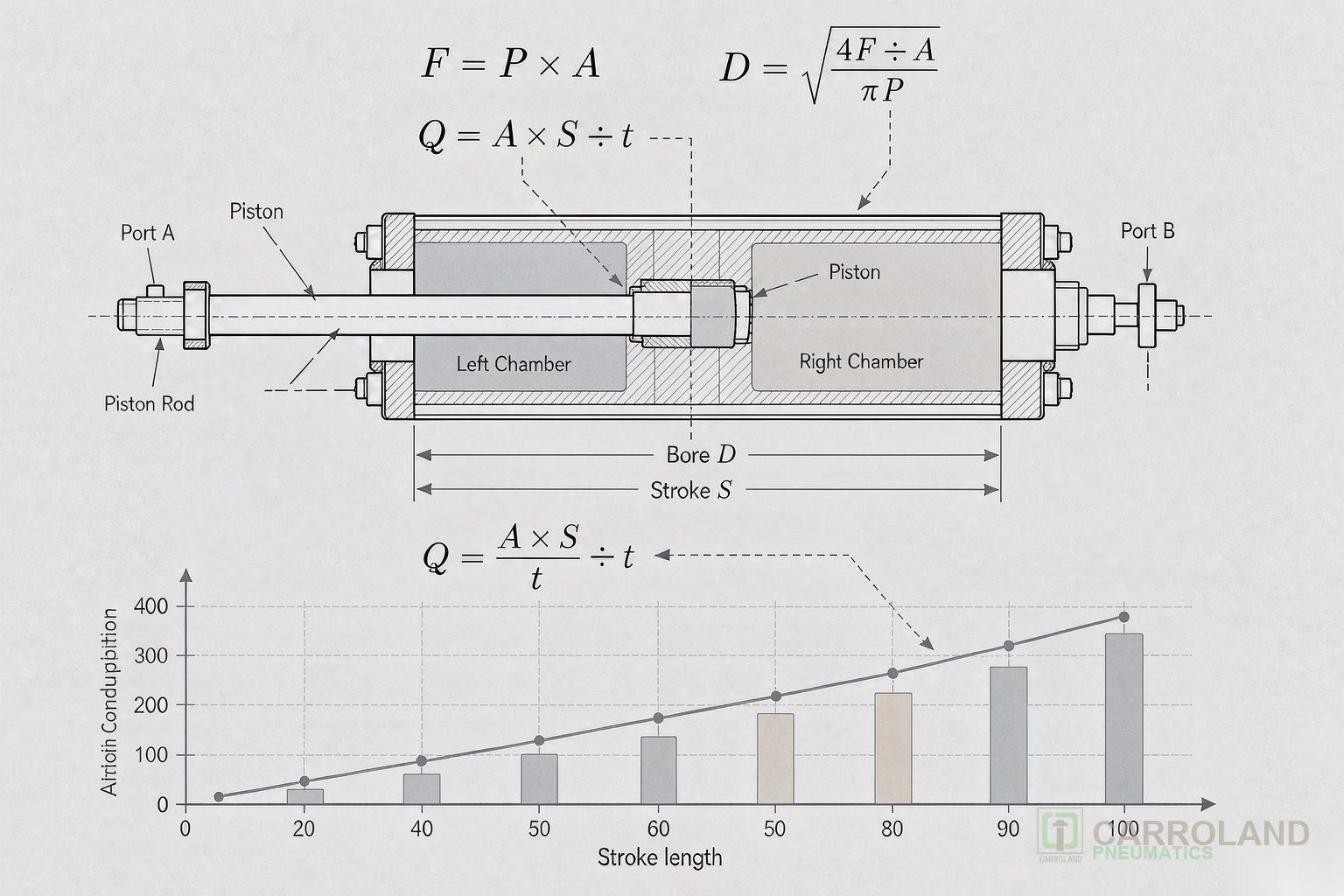
In pneumatics, bore refers to the internal diameter of the cylinder barrel, which fixes the effective piston area and therefore the force available at the rod. For a double-acting cylinder the extend force is piston area multiplied by gauge pressure, while the retract force uses the piston area minus the rod area.
Because force scales with the square of the bore, small changes in diameter have a large effect. A 40 mm bore at 6 bar produces about 754 N of theoretical extend force, and a 50 mm bore produces about 1,178 N, so one standard step up adds more than 50 percent. That is why bore selection, not pressure, is normally the lever used to match a load.
Theoretical Force and Real Load Losses
Theoretical force refers to the simple product of piston area and effective pressure, before friction, seal drag and the pressure drop through the control valve are applied. Real force at the rod is always lower, and the gap widens at low speed and with long tubing runs.
A practical planning figure is to derate theoretical force by 15 to 25 percent for a standard cylinder in good condition. Cylinders with heavy guide loads, side loading or a long unsupported stroke need a larger derating, and a guided or rod-locking design should be considered instead of simply increasing the bore. The control valve matters here as well: a valve with a small flow coefficient drops pressure under the piston and quietly removes force exactly when the cylinder starts to move.
Safety Factor and Load Margin
A design factor called the load margin is applied on top of the derated force, typically 1.5 to 2.0 for static clamping and higher for vertical loads held against gravity. The factor covers seal wear over service life, supply pressure variation across the day, and the difference between a clean new machine and one that has run for two years.
Vertical applications deserve their own review because a stalled cylinder does not simply stop; it drops the load. Holding a vertical load with a standard double-acting cylinder relies on continuous pressure, so a pilot-operated check valve or a rod-locking cylinder is added when the consequence of pressure loss is unacceptable. The safety factor and the holding method should be recorded together on the sizing sheet.
Stroke, Cushioning and Mounting
Stroke selection refers to choosing the travel length together with the cushioning and mounting that keep the rod aligned over that travel. Stroke is set by the motion the machine must perform, plus a small allowance for the cushioning distance at each end so the piston does not drive into the end cap at full speed.
Most cylinders are ordered with adjustable air cushioning, which decelerates the piston in the last part of the stroke and prevents the impact that damages seals and end caps. Long strokes also change the structural picture: a rod that looks adequate at 100 mm can buckle at 500 mm under the same thrust, so the rod diameter is revisited whenever the stroke grows. Mounting style follows from the motion path, with foot, flange and clevis options each fixing the allowed run-out differently.
Air Consumption and Why It Decides the Compressor
Air consumption is a derived figure that multiplies the swept volume of each stroke by the number of cycles per minute and by the absolute pressure ratio, used to size the compressor and the receiver rather than the cylinder itself. It is the number that connects a single actuator decision to plant running cost.
A cylinder that is correctly sized for force can still be an expensive mistake if the cycle rate is high and the air is not recovered. Cushioning, short tubing runs and a correctly sized control valve all reduce consumption, and meters installed on a few representative machines give the most reliable picture of where the compressed air actually goes. For the calculation itself see our air consumption calculation guide.
Working Through a Sizing Example
A sizing example is a worked calculation that turns an assumed load, pressure and stroke into a specific bore and air consumption figure, used to verify that the earlier assumptions hold together. A clamping station that must hold 800 N horizontally, at 6 bar, with a 150 mm stroke and a 10 cycle-per-minute rate, is specified as follows.
The derated target is 800 N divided by 1.8, giving roughly 1,444 N of theoretical force. At 6 bar that points to a 63 mm bore, which produces about 1,870 N theoretical and about 1,500 N after derating, so the margin holds. The stroke is set to 150 mm with cushioning at both ends, the rod is checked for buckling at that length, and the swept volume of both chambers is used to estimate air per cycle. Every value on the sheet traces back to a stated assumption, which is what makes the selection reviewable by the next engineer.
Frequently Asked Questions
These are the sizing questions that come up most often during specification review.
How do I calculate the force of a pneumatic cylinder?
Multiply the piston area by the gauge pressure for the theoretical figure, then derate by 15 to 25 percent for friction and pressure losses, and apply a load margin of 1.5 to 2.0 for the working force.
What bore size do I need to move a given load?
Work backwards from the load: divide the load by the load margin, then pick the smallest standard bore whose derated force at the available pressure exceeds that value.
Does higher air pressure replace a larger bore?
Only up to the pressure the machine can reliably supply. Raising pressure lifts force but also raises air consumption and wear, and many shop floors in India run at a steady 6 bar, so bore is the safer lever.
When does a cylinder need a safety factor above 2.0?
When the load is vertical, when a stall would drop a workpiece, or when the cylinder operates in a dusty or high-cycle environment where seal wear is faster than normal.
Why does air consumption matter for one cylinder?
Because consumption scales with cycle rate across every actuator on the line. A single oversized bore multiplied by hundreds of machines per day becomes a compressor and energy cost, so consumption is sized alongside force.