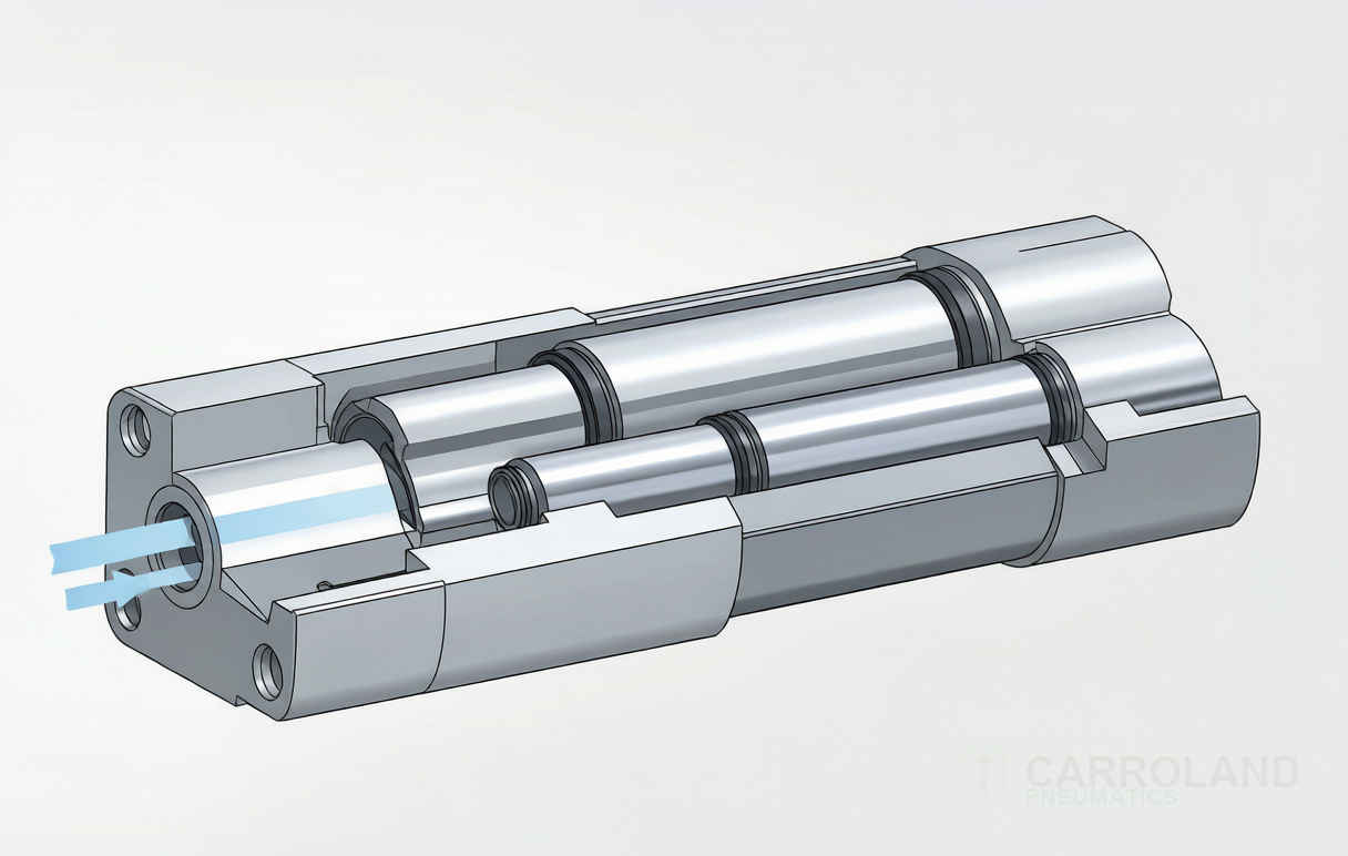
A 3 stage telescopic pneumatic cylinder stacks three concentric barrel sections of decreasing diameter inside a single body. Fully retracted, it occupies roughly one-third of its total stroke length — a 3 000 mm telescopic cylinder retracts to around 1 000 mm. The trade-off is force: each successive stage works on a smaller piston area, so thrust drops by roughly 30-45 % per stage. This makes telescopic pneumatics a specialist choice, not a general-purpose one. Carroland Pneumatics supplies multi-stage pneumatic telescopic cylinders to Indian OEMs where the compact retracted envelope solves a layout problem that a standard ISO 15552 cylinder cannot.
How a 3-stage telescopic pneumatic cylinder works
Compressed air enters the largest (rear) barrel through the base port. The largest-diameter piston extends and carries the medium-diameter barrel with it. Once the medium barrel reaches the end of its travel, an internal shoulder transfers the load to the medium-diameter piston. The medium piston extends and carries the smallest barrel. Once the smallest barrel reaches its stop, the load transfers to the smallest-diameter piston, which extends the piston rod to full stroke.
The key consequence is a stepped force profile. Thrust on the first stage equals pressure times the largest piston area; on the second stage, pressure times the medium area; on the third, pressure times the smallest area. With three equal-stage ratios (each stage bore 70-75 % of the previous one), each stage delivers 50-55 % of the previous stage’s thrust.
| Stage | Typical bore ratio | Thrust @ 6 bar (illustrative, 100 mm rear bore) | Cumulative stroke contribution |
|---|---|---|---|
| Rear (1st) | 1.00 (100 mm) | 4 712 N | ~33 % of total stroke |
| Middle (2nd) | 0.72 (72 mm) | 2 442 N | ~33 % |
| Front (3rd) | 0.52 (52 mm) | 1 275 N | ~33 % |
Where telescopic pneumatic cylinders make sense in India
Most 3-stage telescopic cylinders in industrial service are hydraulic, not pneumatic — the force profile of a 3-stage pneumatic cylinder is too gentle for heavy lifting like tipper trucks, where a hydraulic 3-stage operates at 160-250 bar. But pneumatic telescopics find a niche in applications where the stroke length is the constraint, not the force.
- Container-door and hatch actuation on special-purpose vehicles. A compressed-air system on a municipal waste truck, an airport cargo loader or a defence vehicle can use a 3-stage pneumatic telescopic where the retracted envelope must fit inside the door cavity. Stroke is typically 1 200-2 000 mm.
- Adjustable-height work tables and lift columns. Industrial ergonomic tables that need 600-1 000 mm of vertical adjustment in a 200-300 mm retracted envelope use a 3-stage pneumatic telescopic.
- Light-load dumper and tipping applications below 5 tons. For light-load agricultural tippers, marble slab trolleys and small delivery dump bodies where hydraulic infrastructure is not available, a 3-stage pneumatic telescopic offers a viable alternative.
- Solar-tracker and greenhouse vent actuation. Solar tracker row-spacing actuators and greenhouse roof vents routinely use 3-stage pneumatic telescopic cylinders with 1 500-2 500 mm stroke to span the gap between fixed anchor points.
Sizing the bore for a 3-stage pneumatic telescopic
Sizing starts from the smallest (front) stage because that is the limiting thrust. If the application needs 800 N at full extension at 6 bar, the smallest piston area must deliver at least 800 N, which means a minimum bore of about 42 mm at the front stage. Working backward with a 0.72 stage ratio gives a middle bore of about 58 mm and a rear bore of about 80 mm. The total retracted length is roughly the stroke divided by 3 plus the end-cap thickness.
For Indian operating conditions, two adjustments are worth making to the standard sizing calculation:
- Add a 1.3-1.5× safety factor on the smallest-stage thrust. Indian shop-floor compressors routinely deliver 5.5 bar instead of the 6 bar assumed in the calculation. Thrust drops proportionally.
- Limit the longest stage to 1 500 mm. Beyond 1 500 mm per stage, the unsupported column strength of the smaller-diameter tube becomes the binding constraint, and the cylinder starts to buckle laterally before reaching full thrust.
The cushioning question
Standard 3-stage pneumatic telescopic cylinders are not internally cushioned — air is compressible, and at the end of each stage the full kinetic energy of the moving mass has to dissipate into the trapped air. Without external cushioning or velocity control, the cylinder will slam at each stage transition.
The fix is external flow-control valves on the supply and exhaust lines. A meter-out flow control on the exhaust port regulates the exit velocity of each stage, allowing soft deceleration at the end of stroke. For Indian applications where cycle rates are modest (typically under 10 cycles per minute on tipper or vent actuators) and the moving mass is low, simple needle valves on each port are sufficient.
Compressed-air cost reality
Pneumatic telescopic actuation is significantly more energy-intensive than its hydraulic equivalent. A 3-stage pneumatic telescopic on a 1 500 mm stroke cycle, at 6 bar with a 0.5-second extend-retract cycle, consumes roughly 8-12 standard litres of air per cycle. A 10-cycle-per-minute application is therefore consuming 4 800-7 200 litres per minute of compressed air — about 5-7 kW of compressor power continuously. At Maharashtra industrial tariffs around INR 8.5/kWh, that is INR 12 000-17 000 per month of compressed-air electricity per cylinder, before any leakage losses.
Carroland’s telescopic supply to Indian OEMs
Carroland supplies 2-stage and 3-stage pneumatic telescopic cylinders in standard stroke lengths from 300 mm to 3 000 mm, with bore sizing and end-fitting geometry engineered to the OEM’s mounting envelope. For OEMs evaluating whether a pneumatic telescopic is the right choice — or whether a standard ISO 15552 cylinder with a longer stroke would do the job more economically — see the Carroland guide pneumatic cylinder selection for India and the broader Wikipedia reference on pneumatic cylinders.
FAQ
Can a 3-stage telescopic pneumatic cylinder replace a hydraulic one?
Only at very low force and low cycle-rate applications. Hydraulic telescopics operate at 160-250 bar and deliver far higher thrust in a smaller bore. A 3-stage pneumatic telescopic is appropriate where the compressed-air system already exists, the force requirement is modest (typically under 5 kN at full extension), and the retracted envelope is the binding constraint.
What is the maximum stroke for a 3-stage pneumatic telescopic?
Standard commercial units are available up to 3 000-4 000 mm total stroke. Beyond about 4 000 mm, the unsupported column length of the smallest stage causes buckling problems and the cylinder becomes impractical.
How is the smallest-stage thrust calculated?
Smallest-stage thrust equals operating pressure (bar) × smallest-stage piston area (cm²) × 10. For a 6 bar system with a 50 mm front-stage bore, that is 6 × 19.63 × 10 = 1 178 N theoretical, with a 1.3-1.5× safety factor reducing usable thrust to 785-906 N.
Do telescopic pneumatic cylinders need lubricated air?
Modern Carroland telescopic cylinders use self-lubricating PTFE-impregnated seals that do not require oil in the supply air. The factory air preparation chain (filter + regulator + lubricator, or FRL) should still remove particulate and condensate to ISO 8573-1:2010 Class 1.4.1.