
Electronic Pneumatic Cylinder: Sensor and Control Architecture for Indian Industry
Where “Electronic” Is a Control Architecture, Not a Different Cylinder
When an Indian engineer searches for an electronic pneumatic cylinder, the underlying hardware is usually the same ISO 15552 or ISO 21287 pneumatic cylinder used in on/off service — what changes is the control architecture around it. Electronic control is about how the rod is told where to stop, not about a new pressure medium. The cylinder itself remains a double-acting pneumatic cylinder with a magnetic piston; the difference sits in the upstream electronics — a programmable controller, an integrated position sensor and a proportional or servo valve that throttles flow in real time rather than merely switching it on or off. This is the same family as the electro-pneumatic architecture, with the same accuracy and energy advantages; the term is used interchangeably in industrial catalogues.
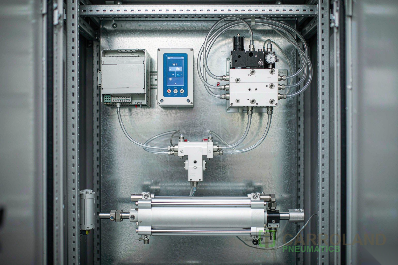
What “Electronic” Adds to a Standard Pneumatic Cylinder
The Three Building Blocks
- Position feedback: typically a magnetostrictive linear position sensor integrated into the cylinder, or a redundant array of Hall-effect switches mounted along the cylinder body and triggered by a magnet on the piston.
- Electronic controller: a PLC, dedicated motion controller or microcontroller running the closed-loop algorithm that compares setpoint and actual position, computes an error, and outputs a control signal to the valve.
- Proportional or servo valve: a five-port valve that throttles flow proportionally to the controller signal, allowing smooth acceleration, deceleration and mid-stroke positioning.
Why Use an Electronic Architecture at All?
Three operational benefits justify the additional cost and complexity. Positioning accuracy improves from ±1–2 mm on an on/off system to ±0.1 mm or better. Energy consumption falls by up to 35 % because the proportional valve supplies only the air needed rather than full-line pressure during the full stroke. Mean time between failures improves by around 40 % as soft stops reduce mechanical shock and seal wear. MTTR improvement comes from the controller’s diagnostic output — fault codes, cycle counts and valve-temperature readings that predict seal and valve wear before failure.
How the Electronic Control Loop Works
- The PLC or controller demands a target rod position.
- The position sensor reports the actual rod position at high frequency.
- The controller computes the error and drives the proportional valve signal.
- The valve modulates cylinder chamber pressure in both directions, accelerating or braking the rod.
- At setpoint, the controller signals the valve to hold pressure against the load, leaving the rod held in place.
A common design rule is that the natural frequency of the control valve must exceed three times the cylinder–load natural frequency for loop stability. Most pneumatic cylinder and load systems behave at 1–5 Hz, well within the capability of modern industrial proportional valves.
Configuration Patterns in Indian Industry
| Architecture | Best Fit | Typical Accuracy |
|---|---|---|
| Proportional valve + linear sensor | Multi-setpoint positioning on assembly machines | ±0.1 mm |
| Servo valve + magnetostrictive sensor | Mid-stroke position and velocity control | ±0.05 mm |
| Solenoid + mechanical brake | End-of-stroke soft stop at lower cost | ±0.5 mm at setpoint |
| PLC counter + reed switches (open loop) | Cycle counting, position verification only | Position confirmed, not controlled |
Selection Criteria for Indian Engineering Teams
Three parameters drive the architecture decision. Required positioning accuracy sets whether a servo valve, a proportional valve, or a soft-stop solenoid-brake is sufficient. Cycle rate sets the natural-frequency requirement of the valve — high-cycle FMCG bottling and EMS pick-and-place demand fast valves; press feeds can run on slower architectures. Air quality sets the FRL specification — proportional valves expect ISO 8573-1 class 2.4.1 or better to keep valve spools from sticking. Carroland India’s range of magnet-equipped ISO 15552 and ISO 21287 cylinders is supplied with the sensor interface and seal compound options for each of the patterns above. For a deeper understanding of how ISO-standard cylinders pair with proportional and servo valve families, see the parent pneumatic cylinder selection guide and the related electro-pneumatic cylinder article.
Frequently Asked Questions
What is an electronic pneumatic cylinder?
A conventional pneumatic cylinder with an electronic position sensor, an electronic controller and a proportional or servo valve, providing closed-loop position control rather than the on/off behaviour of a directional valve.
What is the difference between electronic and electro-pneumatic cylinders?
The terms are used interchangeably in industrial catalogues. They both describe a pneumatic cylinder with electronic control of position and motion. The hardware is the same: cylinder plus sensor plus electronic controller plus proportional valve.
What accuracy does an electronic pneumatic cylinder provide?
Industrial systems commonly reach about plus or minus 0.1 mm positioning accuracy. Premium systems for electronics manufacturing reach 0.01 mm.
What are the energy and maintenance benefits?
Up to about 35 percent energy savings versus on/off systems, and roughly 40 percent longer mean time between failures, due to soft stops reducing mechanical shock and seal wear.
Sources: ISO 15552:2018, ISO 6432:2015; iso.org; Wikipedia: Proportional control.