
What ISO 15552 Mounting Standardisation Means
ISO 15552 cylinder mounting types are defined by the standard so that a cylinder with a given bore can be installed with any of the standard accessories without redesigning the machine interface. The standard fixes the body dimensions, rod thread, and accessory mounting patterns, which means mounting selection becomes a mechanical decision about load path rather than a sourcing constraint. Choosing among ISO 15552 cylinder mounting types correctly is one of the highest-leverage decisions in an actuator specification, because the wrong mount transfers side load into the rod seal and bushing.
The installation decision has two parts: whether the mounting absorbs the reaction force, and whether it permits the small angular misalignment that every real machine frame has. A fixed mount transmits force along a rigid path and tolerates almost no misalignment. A pivoting mount accommodates angular change but needs the load to be guided elsewhere.
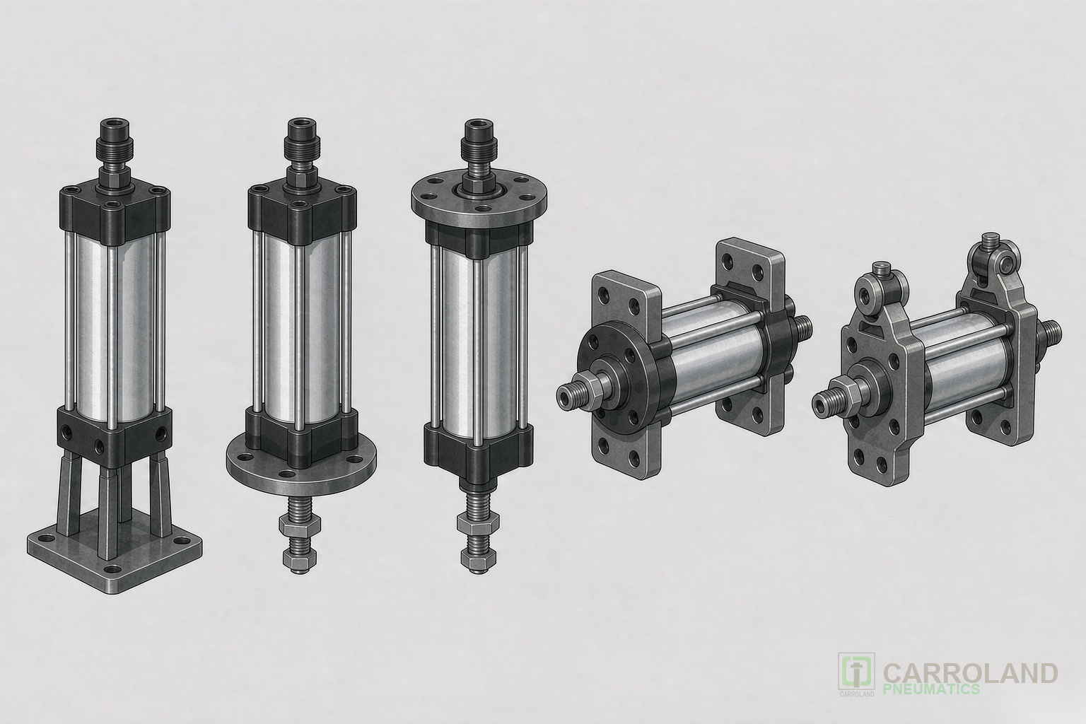
Foot Mounting (LB)
Foot brackets attach to the cylinder end faces and bolt the cylinder down from below or from the side. This is the simplest mount and suits applications where the cylinder pushes a guided load in a straight line.
Foot mounts are rigid in both axes. Any angular misalignment between the rod axis and the load’s travel path produces a bending moment on the rod, which wears the rod bushing and seal. Where alignment cannot be machined accurately, a foot mount should be combined with a floating joint.
Flange Mounting (Front and Rear)
A flange mounts the cylinder by a face perpendicular to the rod axis — a front flange at the rod end, or a rear flange at the cap end. Flanges are chosen when the cylinder must push against a plate or bulkhead and the mounting face is square to the direction of travel.
The distinction matters under load. A front flange places the mounting bolts in tension during the extend stroke; a rear flange places them in compression. For long cylinders under heavy thrust, the flange that keeps bolts in tension generally performs better because bolted joints handle tensile load more predictably.
Trunnion Mounting
A trunnion mount provides pivot pins on the cylinder body, allowing the cylinder to swing as the load moves through an arc. It is the standard choice for applications where the load path is not a straight line — clamps that rotate, hoppers that tip, and linkages that change angle through the stroke.
Trunnion mounting absorbs the reaction force at the pivot, so the load must be guided by the machine, not by the cylinder. The pivot position also determines the moment arm: mounting the trunnion closer to the load reduces the bending moment on the rod.
Clevis and Eye Mounting
A rear clevis or eye mount pivots at the cap end only. The cylinder body swings while the rod end is typically attached with a rod eye or rod clevis. This combination permits angular movement at both ends and is used where the actuator must follow a path that is not known precisely at design time.
Both pivot points should be bushed and greased. A clevis mount with worn pins develops backlash, which shows up as inconsistent end-of-stroke position and accelerated seal wear.
| Mounting type | Absorbs reaction force | Tolerates misalignment | Typical application |
|---|---|---|---|
| Foot (LB) | Yes, rigid | None | Linear push against a guided load |
| Front flange | Yes, bolts in tension on extend | None | Mounting to a plate square to travel |
| Rear flange | Yes, bolts in compression on extend | None | Pushing through a bulkhead |
| Trunnion | Yes, at the pivot | Angular, in one plane | Clamps, tippers, linkages |
| Clevis / eye | Yes, at both pivots | Angular, both ends | Paths not fixed at design time |
Matching the Mount to the Load
The selection sequence is straightforward:
- Determine whether the load is guided by the machine. If yes, a rigid mount is safe. If no, the cylinder must guide the load, which calls for a rod lock, an external guide, or a cylinder with integrated guide rods.
- Determine whether the travel path is straight or arc-shaped. Arc-shaped paths require a pivoting mount.
- Determine the direction of the dominant thrust, then choose the flange orientation that suits it.
- Confirm the mounting pattern matches the bore, since accessory dimensions are standardised per bore size.
Side load is the enemy of cylinder life regardless of mounting type. Where any misalignment is expected, a floating joint between the rod and the load is inexpensive insurance: it compensates for parallel and angular offset without transmitting the moment into the rod.
Mounting and Air Supply
Mounting choice also affects serviceability and air supply. A cylinder mounted in a cramped bay is harder to reach for seal replacement and sensor adjustment, and long supply tubing to a remote cylinder adds dead volume that must be filled and exhausted on every cycle. Where consumption matters, the volume of the supply line is part of the calculation described in the pneumatic cylinder air consumption calculation.
Air quality applies equally to mounting: contaminated air accelerates rod bushing wear, which is exactly the component that misalignment also damages. Supply condition classes are defined in the ISO 8573-1 air quality classes for FRL selection.
Sensor Mounting and Position Feedback
Cylinders built to this standard commonly include a slot along the body for position sensors used with a magnetic piston. When the mounting is a foot or flange, the sensor slot should face outward — mounting the cylinder with the slot against the machine frame makes sensor adjustment impossible without dismantling the cylinder. This is a frequent installation oversight discovered only at commissioning.
Where position feedback is used for sequencing, the control valve‘s centre behaviour governs what happens during a pause or a power loss; that decision is covered in the comparison of 5/2 and 5/3 valve configurations.
Where Compact and Small-Bore Designs Differ
The mounting logic described here applies to the larger industrial bore family. Compact cylinders in the smaller bore range use a different set of standardised accessories and shorter strokes, and their selection is driven primarily by available axial space. The bore families and their dimensional relationships are covered in the ISO 21287 compact cylinder selection guidance and in the dimensional verification comparison for the larger and smaller industrial families.
FAQ
Which ISO 15552 mounting type tolerates misalignment best?
Clevis and eye mounts, because they pivot at both ends. Trunnion mounts tolerate angular movement in one plane. Foot and flange mounts are rigid and require accurate alignment or a floating joint.
Should I use a front or rear flange?
It depends on the dominant thrust direction. On the extend stroke a front flange puts the mounting bolts in tension and a rear flange puts them in compression; bolted joints generally behave more predictably under tension.
What causes premature rod seal wear on a rigidly mounted cylinder?
Side load from misalignment between the rod axis and the load path. The resulting bending moment wears the rod bushing and seal. A floating joint or a pivoting mount removes the moment.
Do mounting accessories fit any bore size?
No. Accessory dimensions are standardised per bore size, so the bracket, flange, or clevis must be specified for the same bore as the cylinder.